
avr Control 5V buzzer using mcu and a single 5 V power supply

The circuit involves utilizing a PB-12N23PW-05Q buzzer with an ATmega 162 microcontroller, necessitating careful consideration of the current requirements and voltage levels to ensure proper functionality. The buzzer's current draw exceeds the ATmega's maximum output capability, necessitating the use of a switching component. The chosen BD237 NPN transistor serves as a switch, controlled by the microcontroller's output pin. However, due to the inherent voltage drop across the transistor, the buzzer may not receive sufficient voltage for reliable operation.
To enhance performance, it is advisable to incorporate a base resistor (1 KOhm) between the microcontroller and the transistor's base. This resistor helps limit the base current, protecting the microcontroller from excessive current draw. The output from the transistor should be monitored to ensure that the voltage across the buzzer remains within the specified range of 4.5 to 5.5 V. If the voltage drop across the transistor is significant, switching to a MOSFET with lower on-resistance is recommended. The 2N7000 MOSFET, for instance, presents a more efficient solution, minimizing voltage loss and allowing the buzzer to operate effectively.
In practical applications, testing the buzzer with a variable power supply can provide insights into its operational characteristics. Observing the voltage levels with an oscilloscope can reveal potential issues such as voltage drops during peak current demands, which may lead to microcontroller resets. To address these concerns, adding bypass capacitors near the power supply lines can stabilize the voltage supplied to the microcontroller and the buzzer, while a ferrite bead or resistor can help filter out any high-frequency noise.
Overall, careful design considerations, including component selection and circuit configuration, will ensure that the buzzer operates reliably within the constraints of the ATmega 162 microcontroller.A PB-12N23PW-05Q buzzer and I`m trying to use it with ATmega 162. I can`t connect it directly to pin, because from what I`ve read from 162`s datasheet, it can source at most 20 mA. The buzzer takes 50 (or around 25, if we take a look at the graph), so I don`t think I can just directly connect it to the microcontroller.
My initial idea was to connect it to a transistor and use the transistor as a switch. Unfortunately, it didn`t work. I used BD237 and my idea was that the microcontroler will pull the pin connected to the base high and the transistor will operate the buzzer. In my setup, I had buzzer connected to Vcc, buzzer`s negative port connected to collector, GND connected to the emitter and 162 connected to the base.
Transistor is of NPN type. Somewhere I read that this way some problems related to the voltage drop on the transistor can be mitigated, but to me it looks like the voltage drop is the main problem here. @AndrejaKo The micro does not have a resistor inside the pin. It only has a maximum specified output current which, when exceeded, may release magic smoke. Use Ohm`s law to specify the resistor. joeforker Feb 14 `11 at 22:59 Thank you for posting and linking to exactly which sound-maker you are trying to use: the PB-12N23PW-05Q self-oscillating buzzer.
(If you had a raw piezo disk, or a coil speaker, we would use a different drive circuit). If you insist on using a NPN such as the BD237, you need to add a external resistor between the MCU and the base of the NPN, as joeforker mentioned: 1 KOhm should be adequate. But no matter what resistor or silicon NPN transistor you use, you will end up with (at best) a V_ce_sat voltage drop of around 0.
6 V, so the voltage across the buzzer is about 4. 4 V - which is technically outside the "guaranteed-to-work" "4. 5 to 5. 5 V" operating range in the buzzer datasheet. If I were you, I would probably throw out the NPN and replace it with a MOSFET. A cheap 2N7000 has an on-resistance of 5 Ohm; at 25 mA that gives a voltage drop of. 125 V. (More expensive MOSFETs have an order of magnitude less (better) on-resistance). Hook the buzzer up to a bench power supply, and see what it sounds like in the 4 V to 5 V voltage range. Perhaps it`s supposed to sound like that at that (5V - transistor drop) voltage What is the actual voltage across the buzzer and across the transistor I might check this with an O`scope, since it`s quite possible that we have an average current of 25 mA, as shown on the graph, but peak pulses of much higher current - perhaps such a high instantaneous current that your so-called "5 V" power supply is briefly pulled down to such a low voltage that your ATmega resets.
If that is the case, you`ll need to add some bypass capacitors and perhaps a ferrite bead or resistor. 🔗 External reference
Related Circuits
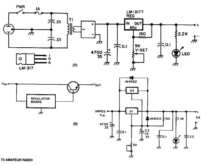
Universal Power Supply Module 3V-30V power supply. Refer to the specified page for an explanation of the related circuit diagram. This power supply circuit is paired with a high-power audio amplifier rated at 1500 watts. The design of the...
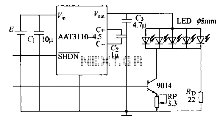
A circuit designed for a phone photo camera flash that delivers a peak current of 200mA. It utilizes the AAT3110-4.5 capacitive charge pump chip to boost and regulate the lithium battery voltage to 4.5V. This voltage powers a series...
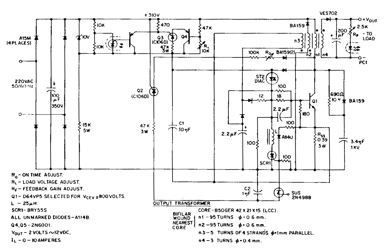
This low-voltage, high-current output switching power supply operates from a 220 VAC input. In this circuit, an ST2 diac relaxation oscillator, along with Q3, C1, and the diac, initiates the conduction of the output switching transistor Q1. The on-time...
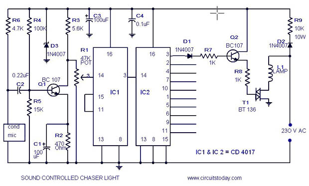
A simple musical light chaser circuit diagram and schematic using IC CD4016. This circuit blinks lights in response to sound, audio, or music output, causing 10 lights to dance according to sound frequency. The musical light chaser circuit utilizing the...
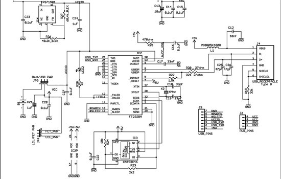
As found in SLAA458, the revised pulse oximeter application, an image of the USB schematic is attached, which is used to output collected data. There are a few questions regarding this schematic: 1) What do J3 and J6 correspond...
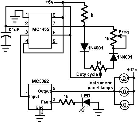
This circuit utilizes an MC3392 low-side protected switch along with an MC1455 timing circuit to create a dimmer control for automotive instrumentation panel lamps. The brightness of incandescent lamps can be adjusted by applying Pulse Width Modulation (PWM) to...