
Musical Light Chaser Circuit with Diagram using IC CD4016

The musical light chaser circuit utilizing the CD4016 integrated circuit is designed to create a visual display that synchronizes with audio inputs. The CD4016 is a quad bilateral switch, which allows for the control of multiple outputs based on the audio signal's characteristics.
In this circuit, the audio input is fed into the CD4016, which processes the signal and activates a series of connected LEDs. The arrangement of the LEDs is such that they illuminate in a sequential pattern, creating a "chaser" effect. The number of LEDs used can vary, but in this case, 10 LEDs are employed to provide a visually engaging experience.
The circuit typically includes a power supply, which can range from 5V to 15V, depending on the specifications of the LEDs used. A resistor is placed in series with each LED to limit the current and prevent damage. Additionally, capacitors may be integrated into the design to filter the audio signal and smooth out any fluctuations, ensuring a more stable output.
The operation of the circuit relies on the characteristics of the input audio signal. As the sound frequency changes, the CD4016 responds by turning on and off different LEDs in a way that reflects the rhythm and intensity of the audio. This creates a dynamic visual representation of the sound, making it suitable for applications such as parties, performances, or as a decorative element in home audio systems.
Overall, this simple yet effective circuit demonstrates the integration of audio signals with visual displays, showcasing the versatility and functionality of the CD4016 IC in creating engaging electronic projects.A simple musical light chaser circuit diagram and schematic using IC CD4016. This simple circuit blinks light according to sound/audio/music output and as a result 10 lights dance according to sound frequency.. 🔗 External reference
Related Circuits
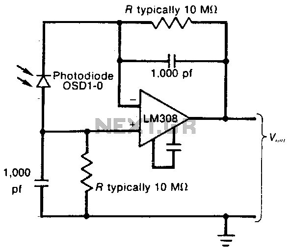
This circuit employs a low-input-bias operational amplifier (op amp) to provide a stable DC indication of light levels. To decrease the sensitivity of the circuit to light, the resistor Rl can be reduced, although it should not be set...
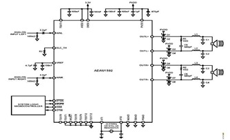
This is a typical stereo application circuit schematic of the ADAU1592, a 2-channel, bridge-tied load (BTL) switching audio power amplifier. The ADAU1592 can be utilized in flat panel televisions, PC audio systems, and mini-component applications. The ADAU1592 is designed to...
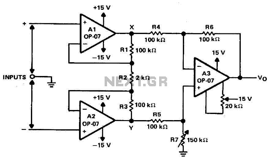
Operational amplifiers A1 and A2 are connected in a non-inverting configuration to form amplifier A3. The operational amplifier A3 can be classified as a subtractor circuit that converts the differential signal between the floating points X and Y into...
This circuit is a wireless car alarm system composed of two modules: a transmitter and a receiver. It operates using FM radio waves and is compatible with vehicles that have a 6-12V DC power supply. If the vehicle's power...
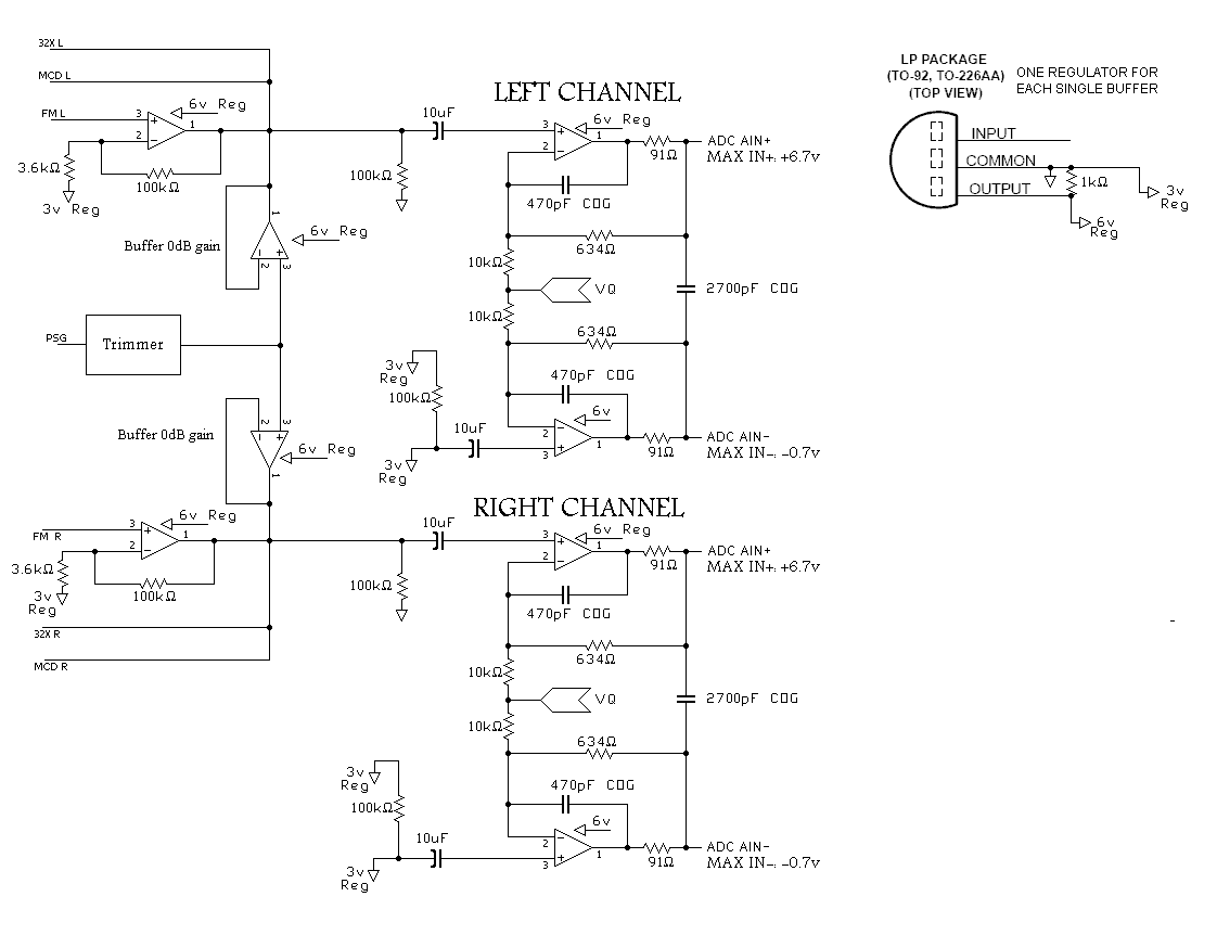
A program is needed to set the channels to their maximum level or to write the full scale to the Digital-to-Analog Converter (DAC). The MD schematics indicate that the audio signals are mixed with ratios of 0.0431 for the...

The DC motor E inversion control circuit utilizes a loop configuration with various relay contacts. It employs a single set of normally open/normally closed relay contacts. When both inputs A and B are low, relay KI is activated. In...