
Doppler Ultrasound Transmitter Circuit

The circuit consists of a 2.25-MHz oscillator (Q1) that serves as the primary frequency generator. This oscillator is crucial for producing the high-frequency signal required for the operation of the ultrasonic transducer, which in this case is a lead zirconate-titanate (PZT) type. PZT materials are known for their piezoelectric properties, allowing them to convert electrical energy into mechanical vibrations, which are essential for ultrasonic applications.
The output from the oscillator (Q1) is fed into amplifier Q2. The role of this amplifier is to strengthen the signal generated by the oscillator, ensuring that it is sufficiently powerful to drive the ultrasonic transducer effectively. This amplification is critical, as the transducer requires a certain level of input power to operate efficiently and produce the desired ultrasonic waves.
Additionally, the circuit includes taps on transformers T1 and T2, which are designed to provide low-impedance drive points. These taps facilitate the connection of the oscillator and amplifier to the transducer while minimizing losses and ensuring that the signal remains strong and stable. The low-impedance characteristic is particularly important in high-frequency applications, as it helps to reduce reflections and improve overall circuit performance.
In summary, this circuit configuration is optimized for ultrasonic applications, leveraging the properties of the lead zirconate-titanate transducer, while ensuring robust signal amplification and efficient power delivery through the use of low-impedance drive points. The 2.25-MHz.osciJlator Ql drives amplifier Q2 and XTAL1, an ultrasonic transducer. The transducer is a lead zireonate-titanate type. Taps on Tl and T2 provide low-impedance drive points.
Related Circuits
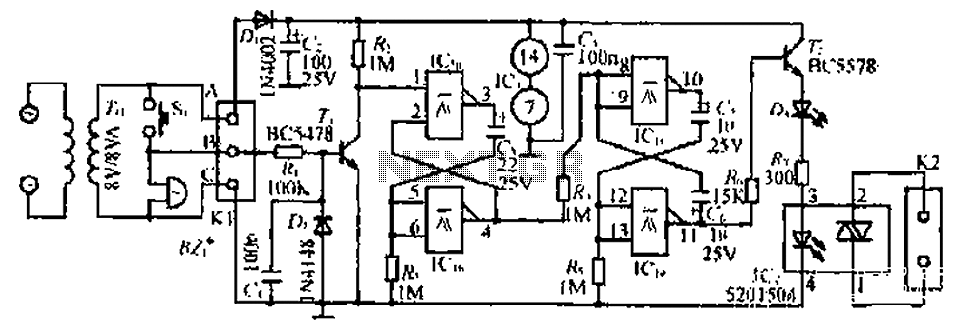
The circuit with the original m rJ bamboo is designed similarly. It includes a secondary disk that functions as a floodlight. A grass-flow filter is incorporated for a light input. An electric connection is established with a door button...
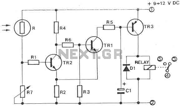
The circuit is a light switch that activates when the light intensity drops on a photoresistor. It features a straightforward construction and can be utilized in numerous applications. The photoresistor and the trimmer function as a voltage divider and...
A touch switch is a switch that is turned on and off by touching a wire contact, instead of flicking a lever like a regular switch. Touch switches have no mechanical parts to wear out, so they last a...
Police siren circuit diagram. This circuit produces a sound similar to a police siren. It utilizes two 555 timer ICs. The police siren circuit typically employs two 555 timer integrated circuits (ICs) configured in astable mode to generate a square...
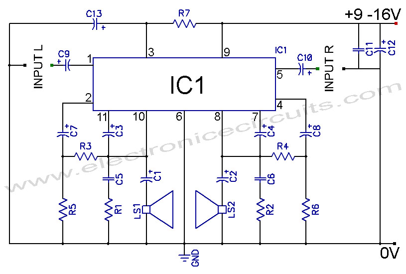
TDA2004 Car Battery 12W Stereo Amplifier Circuit. Its main features are low distortion, low noise, and high reliability of the chip. The TDA2004 is a highly integrated audio amplifier designed specifically for automotive applications. This circuit is capable of delivering...
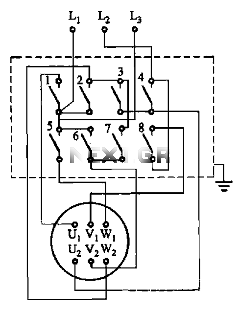
The circuit illustrated in Figure 3-36 includes the starter contact closure detailed in Table 3-1. In the figure, U1, V1, W1, and U2, V2, W2 represent the first three-phase stator windings of the motor terminals. The circuit depicted in Figure...