
Background music decoder

The background music (SCA) decoder circuit utilizes the NE565 PLL IC to effectively demodulate and decode the subcarrier audio signals embedded within a multiplexed FM broadcast. The NE565 is capable of locking onto the frequency of the SCA signal, which typically operates at a frequency of 67 kHz, allowing for the extraction of the audio content.
The circuit configuration includes the necessary components to filter and amplify the input FM signal before it reaches the NE565. This may involve the use of RF amplifiers and bandpass filters to ensure that the desired frequency range is isolated while minimizing noise and interference. The output of the NE565 is then processed through additional audio filters to remove any residual carrier frequencies and enhance the quality of the decoded audio signal.
Power supply considerations are also critical in this design, with appropriate voltage regulation and decoupling capacitors included to ensure stable operation of the NE565 and prevent power supply noise from affecting the performance of the circuit. The output can be connected to audio amplification systems or directly to speakers, depending on the application requirements.
Overall, this background music decoder circuit effectively utilizes the NE565 PLL IC to achieve reliable demodulation of SCA signals, providing a clear and high-quality audio output suitable for various applications in broadcasting and audio distribution.This is a background music (SCA) decoder circuit from the input demodulated (multiplex) FM signal. We use NE565 (Phase Locked Loop IC) to be base of this.. 🔗 External reference
Related Circuits
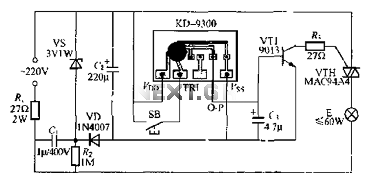
The circuit utilizes a KD-9300 music IC, which activates when the button switch (SB) is pressed, causing the electric lamp (E) to light up for approximately 20 seconds before automatically turning off. The setup includes a half-wave rectifier and...
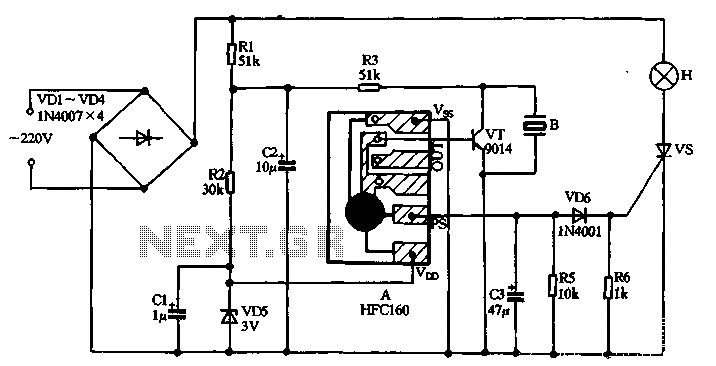
220V AC power is supplied through a VD1 to VD4 bridge rectifier and a voltage regulator circuit involving R1, R2, and VD5 components. The output provides a DC voltage of approximately 3V, which powers the manifold A. The manifold...
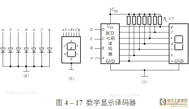
The luminescent diode (LED) is constructed from gallium arsenide (GaAs), a specialized semiconductor material, and gallium arsenide phosphide. It can be used individually or assembled into segment-type or lattice LED display devices. The display unit consists of a sectional...
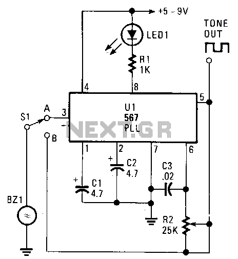
The transducer circuit can function as either a tone encoder or decoder by adjusting the position of switch Sl. The operating frequency of this dual-purpose circuit is set by capacitors C3 and resistor R2. Capacitors C1 and C2 are...
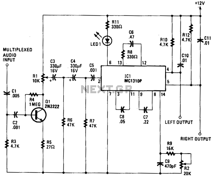
The composite input signal is amplified by transistor Q1 and is then connected to a high-pass filter consisting of capacitors C3 and C4, along with resistors R6 and R7. The filtered audio signal is subsequently sent to IC1, which...
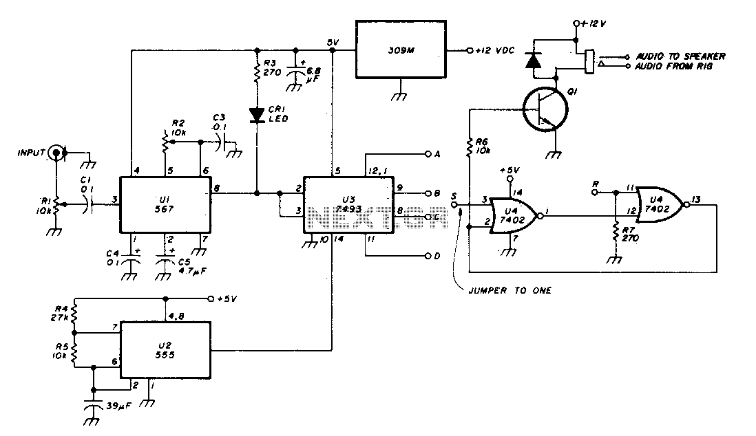
The Phase-Locked Loop (PLL) integrated circuit (U1) is configured with resistor R2 to achieve the desired tone frequency. An LED indicator is used to show when the PLL has locked onto the signal. To ensure proper lock-up, the signal...