
HFC lantern making music controller circuit

The circuit described utilizes a 220V AC input that is converted to a usable DC voltage through a bridge rectifier composed of diodes VD1 to VD4. This configuration allows for full-wave rectification, providing a smoother DC output suitable for powering subsequent components. The voltage regulator circuit, incorporating resistors R1 and R2 along with diode VD5, ensures that the output voltage is stabilized at approximately 3V, which is essential for the reliable operation of the manifold A.
The manifold A serves a dual purpose: it not only powers the circuitry but also generates a beat signal at the Ps output. This signal is crucial for controlling the timing of the SCR (Silicon Controlled Rectifier) operation. The timing is adjusted using capacitor C3 and resistor R5; their values can be modified to change the delay period, thus affecting the rate at which the SCR turns on and off. This feature allows for customization of the flashing duration, which can be particularly useful in applications requiring visual signaling or effects.
The electronic music component of the circuit is facilitated by the OUT output, which connects to a transistor (VT). This transistor acts as a switch that drives a piezoelectric ceramic sheet B, enabling the production of sound. The piezoelectric element converts electrical signals into mechanical vibrations, generating audible sound waves that correspond to the electronic music signals processed by the circuit. The overall design illustrates a basic yet effective method for combining power rectification, signal modulation, and sound generation in a compact electronic system.220V AC power via VD1 ~ VD4 bridge rectifier and voltage regulator circuit through R1, R2, VD5 cl composition and output DC voltage of about 3V, the manifold A supply of electricity. Manifold output of the beat the beat signal Ps output from C3, R5 configured to control a part of the delay of the SCR vs turned on and off. C3 and R5 values can be adjusted to change the duration of the flashing between. Manifold music signal output from the OUT output by the transistor VT zoom, push the piezoelectric ceramic sheet B makes a musical movement listening to electronic music sound.
Related Circuits
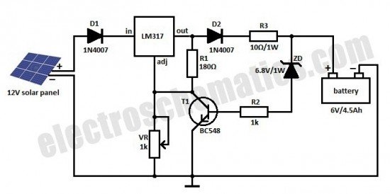
This is a solar charger circuit designed to charge Lead Acid or Ni-Cd batteries using solar energy. The circuit captures solar energy to charge the batteries. The solar charger circuit typically consists of several key components, including a solar panel,...

These circuits are commonly utilized in robotics to enable DC motors to operate in both forward and reverse directions, as well as to provide an electric brake (short circuit condition). H-bridges can be found as integrated circuits or can...
Approximately one watt RMS appears to be a suitable output level, which is also the maximum power that a basic amplifier powered by 12V can deliver to an 8 Ohm speaker. A very low saturation amplifier may reach up...
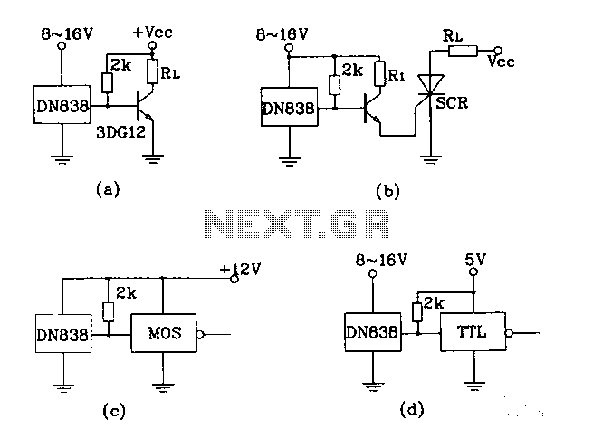
Figures (A), (B), (C), and (D) illustrate outputs that can directly drive transistors, thyristors, relays, CMOS circuits, and TTL circuits. The described figures depict various output configurations capable of interfacing with different electronic components. Each output is designed to provide...

This device acts as a variable speed control for the heater blower in a car. It takes its power directly from the existing wiring and connects with just 2 wires. It will also work for any 12 volt device...
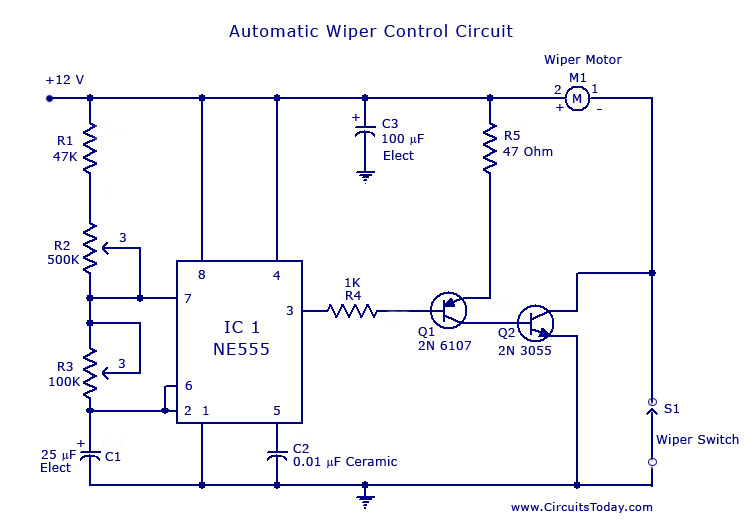
A circuit for car windshield/wiper motor speed control built using an NE 555 IC. This enables intermittent windshield wiper control, which changes the sweep rate to 10 seconds. The circuit utilizes the NE 555 timer IC configured in astable mode...