
BALANCED MODULATOR DEMODULATOR

The described circuit is a diode quad modulator designed to effectively suppress carrier signals by 65 dB, as indicated in the reference by W. H. Ellis. This suppression is critical in applications where signal fidelity is paramount, such as in communication systems. The use of closely matched diodes is essential for maintaining consistent performance across the modulation spectrum.
In this configuration, R1 serves as the primary amplitude adjustment component, allowing the user to fine-tune the output signal's amplitude to meet specific requirements. The coaxial line, which is integral to the circuit, is used for precise phase adjustment, ensuring that the modulation is aligned correctly with the carrier signal. This alignment is crucial for minimizing distortion and maximizing the quality of the output signal.
R2, while providing a more minor adjustment, plays a significant role in refining the overall performance of the circuit. By allowing slight variations in amplitude, R2 aids in achieving optimal signal characteristics, which can be particularly beneficial in systems where signal levels may fluctuate due to varying operational conditions.
The overall design emphasizes the importance of component matching and careful adjustment to achieve high levels of suppression, making this circuit suitable for advanced communication applications where clarity and precision are required.Achieves high carrier and modulation suppression by using closely matched diodes and providing R1 for amplitude adjustment and coaxial line for phase adjustment. R2 provides slight amplitude adjustment. -W. H. Ellis, Diode Quad Modulator Suppresses Carrier 65 Db, Electronics, 39:8, p 97. 🔗 External reference
Related Circuits
Burr-Brown DRV134 audio balanced line receiver schematic PCB/kit available? There is an interest in creating a balanced line receiver using the DRV134. The Burr-Brown DRV134 is an integrated circuit designed for audio applications, specifically for converting unbalanced audio signals...
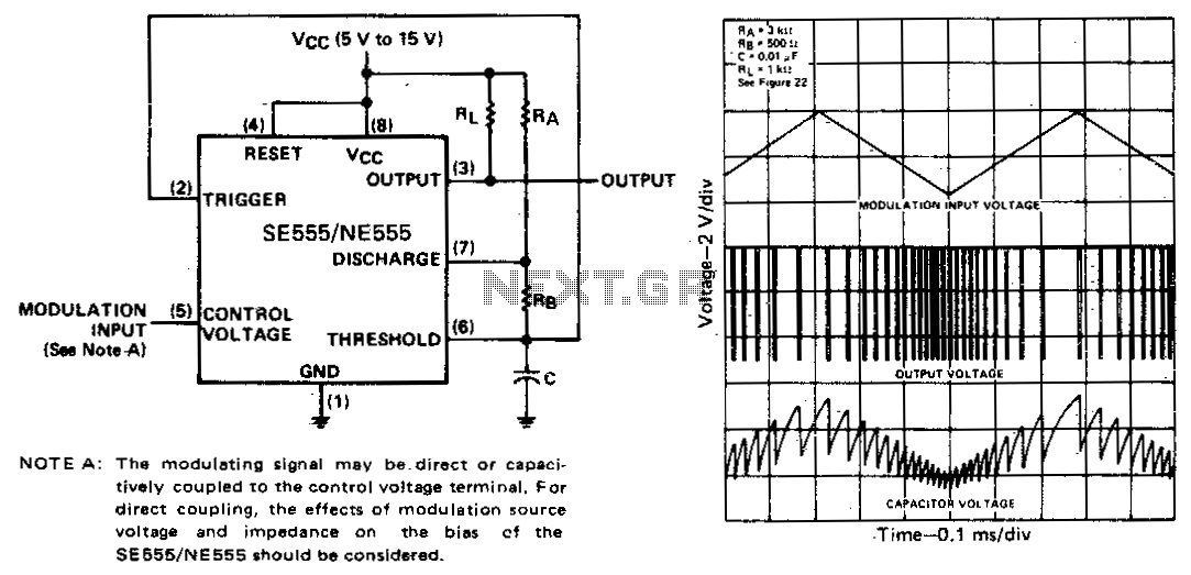
The threshold voltage, and consequently the time delay, of a free-running oscillator is depicted as being modulated by a triangular-wave modulation signal. However, any type of modulating wave shape could be employed. In a free-running oscillator circuit, the threshold voltage...
An AM modulator for the medium wave (MW) band enables playback of music from a CD or MP3 player on compatible radios during the daytime. This device is not classified as a transmitter due to its low output power...
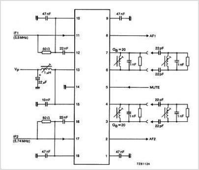
The TDA3567 is a monolithic integrated decoder designed for the NTSC color television standards. It incorporates all the necessary functions for the demodulation of NTSC signals. Additionally, it features a luminance amplifier and an RGB matrix amplifier. These amplifiers...
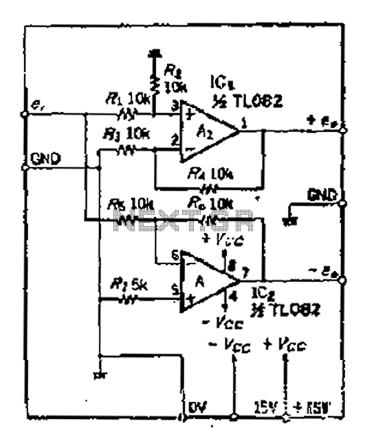
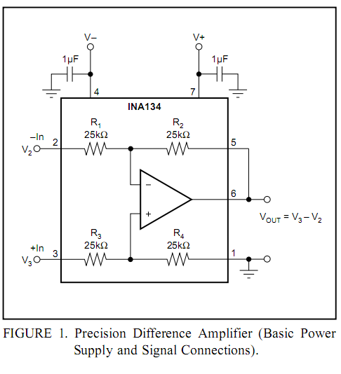
A balanced output is often associated with the positive phase amplifier output terminal of an operational amplifier, which is typically viewed as the inverting amplifier circuit. However, the reversed phase output can lead to a loss of balance in...
A pulse width modulator generates a PWM signal, which consists of pulses with a constant frequency while the duty cycle varies according to a modulating signal. A pulse width modulator (PWM) is an essential component in various electronic applications, particularly...