
Pulse-position modulator

In a free-running oscillator circuit, the threshold voltage plays a critical role in determining the oscillation frequency and the time delay between successive cycles. The modulation of this threshold voltage using a triangular-wave signal allows for dynamic control over the oscillator's output frequency. The triangular wave provides a linear ramp-up and ramp-down of voltage, which influences the timing of the oscillator's transitions between its high and low states.
The free-running oscillator typically consists of an active device, such as a transistor or operational amplifier, configured in a feedback loop. The output signal from the oscillator can be fed back to the input through a resistor-capacitor (RC) network that sets the timing characteristics of the oscillator. By integrating a modulation signal, such as a triangular wave, into the feedback loop, the threshold voltage can be adjusted in real-time, resulting in a variable frequency output.
In addition to triangular waves, other wave shapes, such as square waves, sine waves, or sawtooth waves, can also be utilized for modulation. Each wave shape will produce different effects on the oscillator's performance, allowing for a variety of applications in signal generation, frequency modulation, and waveform shaping. The choice of modulation waveform will depend on the specific requirements of the application, including the desired frequency range and the nature of the output signal.
Overall, the implementation of a modulated threshold voltage in a free-running oscillator circuit provides enhanced flexibility and control, enabling the generation of complex waveforms suitable for various electronic applications.The threshold voltage, and thereby the time delay, of a free-running oscillator is shown modulated with a triangular-wave modulation signal however, any modulating wave-shape could be used.
Related Circuits
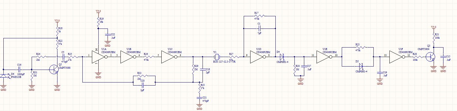
The circuit receives a 32.768 kHz infrared (IR) input and produces a logic low output when the input signal is detected. The design consists of three distinct stages: the section up to U1A, the section between U1A and Q3,...
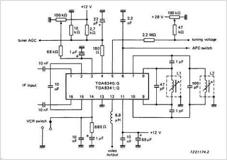
The TDA9813T is an integrated circuit designed for processing vision intermediate frequency (IF) signals and dual frequency modulation (FM) demodulation of sound. It operates with a single reference QSS-IF in television (TV) and video cassette recorder (VCR) applications, specifically...
Early in the exploration of high-power LEDs, such as the Luxeon 1 and 3-watt devices, the potential of Pulse Width Modulation (PWM) techniques for LED modulation was considered. This method theoretically minimizes distortion by making the LED's "Current versus...
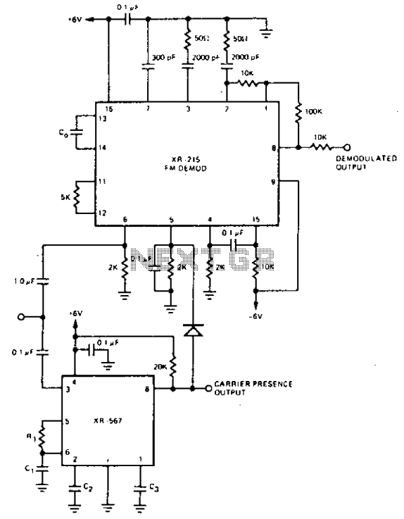
For FM demodulation applications where the bandwidth is less than 10% of the carrier frequency, an XR-J567 can be used to detect the presence of the carrier signal. The output of the XR-567 is used to turn off the...
The STK672-050 is a unipolar constant-current chopper-type externally-excited 4-phase stepping motor driver hybrid integrated circuit (IC) that utilizes MOSFET power devices. It features a built-in microstep operation-supported 4-phase distributed controller, enabling the realization of a high torque, low vibration,...

The basic current allows no carrier to be present in the output. By adding offsets to the carrier differential pairs, controlled amounts of carrier appear at the output. The amplitude becomes a function of the modulation signal—AM modulation. In a...