
BALANCED MODULATOR FOR ADF
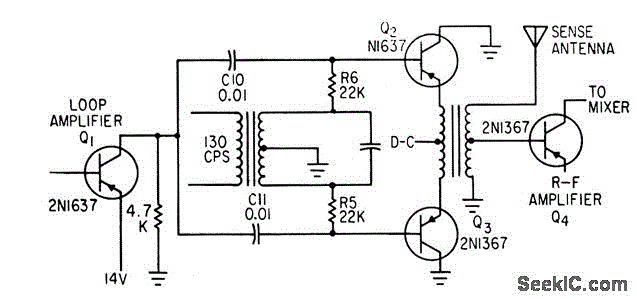
The circuit described is integral to the operation of an automatic direction finder (ADF), which is essential in navigation systems. The primary function is to combine the signals received from loop and sense antennas, allowing for accurate directional information to be extracted.
The loop antenna is designed to pick up signals from a specific direction, while the sense antenna captures signals from all directions. The combination of these signals is crucial for determining the angle of arrival of a radio frequency signal. The output frequency of 130 cycles per second (cps) is significant, as it is tuned to the operational requirements of the resolver, which is a type of rotary electrical transformer used for measuring angular position.
The circuit employs phase manipulation techniques to ensure that the output signal is correctly phased. This is essential for the rotor of the resolver to be driven to the null position, indicating that the ADF is accurately aligned with the incoming signal. By achieving this null position, the system can provide precise directional information, which is vital for navigation and positioning applications.
The implementation of servo filters and gain control within the circuit enhances the performance of the ADF. Servo filters help in stabilizing the output signal by filtering out noise and unwanted frequencies, while gain control adjusts the amplitude of the output signal to ensure optimal performance under varying signal conditions.
Overall, this circuit plays a critical role in the functionality of automatic direction finders, contributing to the accuracy and reliability of navigation systems in various applications, including aviation, maritime, and land-based navigation.Combines signals from loop and sense antennas of automatic direction finder, to give 130-cps output having correct phase for driving rotor of resolver to null position.-P. V.Sparks, Servo Filter and Gain Control lmprove Automatic Direction Finder, Electronics, 34:23, p 110-113..
🔗 External reference
Related Circuits
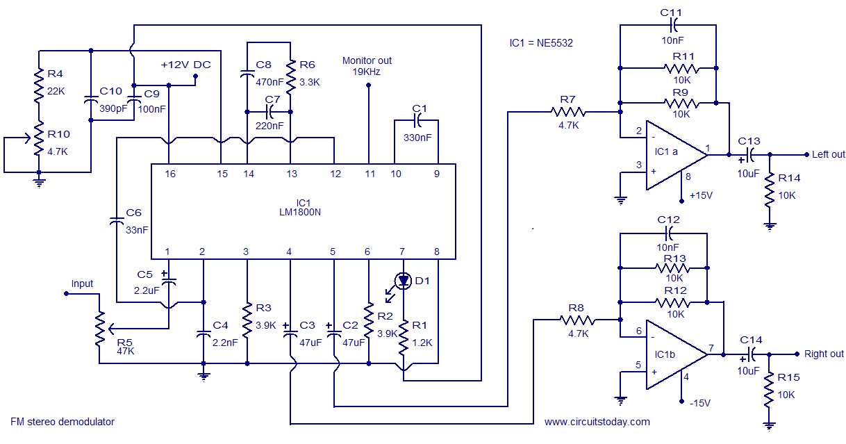
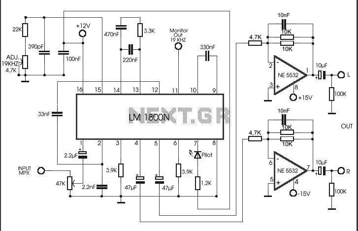
The LM1800 is an integrated FM stereo demodulator IC that incorporates several beneficial features, enabling the design of a high-quality FM stereo demodulator system with excellent sound quality. The LM1800 utilizes phase-locked loop technology to regenerate the 38 kHz...
A monolithic phase locked loop for data communications. The IC contains a basic phase locked loop for tracking an input signal within the pass band, a quadrature phase detector which provided carrier detector and an FSK voltage comparator which...
Construct an accurate LC Meter (Capacitance Inductance Meter) to facilitate the creation of coils and inductors. This LC Meter is capable of measuring very small inductances, making it an ideal tool for various RF coil and inductor applications. The...
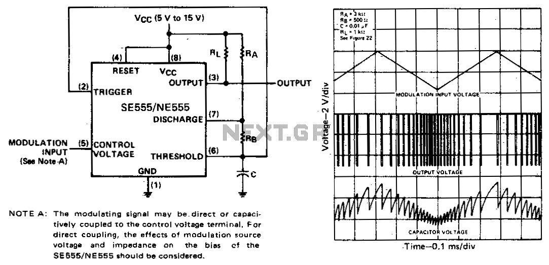
The threshold voltage, and consequently the time delay, of a free-running oscillator is depicted as being modulated by a triangular-wave modulation signal. However, any type of modulating wave shape could be employed. In a free-running oscillator circuit, the threshold voltage...
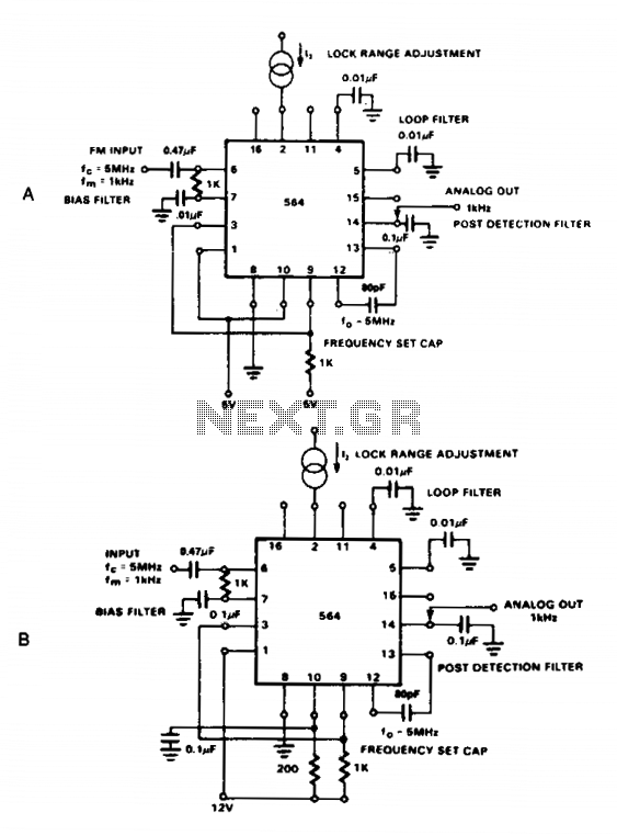
The NE564 functions as an FM demodulator. The operational connections for both 5 V and 12 V configurations are illustrated in Figures 21-4A and 21-4B. The input signal is AC coupled, with the output signal extracted from Pin 14....
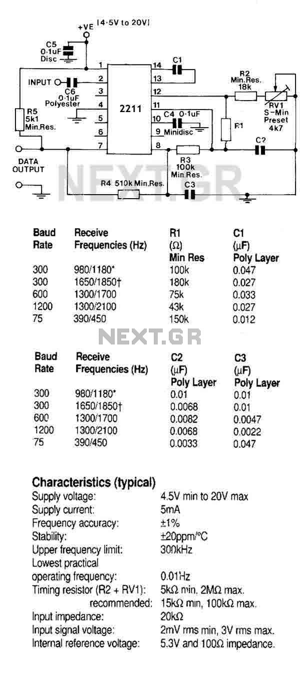
The FSK demodulator is an electronic device that converts the FSK signal into a serial digital signal. FSK modulation is utilized to transmit digital serial data. The FSK (Frequency Shift Keying) demodulator serves a critical function in digital communication systems...
Warning: include(partials/cookie-banner.php): Failed to open stream: Permission denied in /var/www/html/nextgr/view-circuit.php on line 713
Warning: include(): Failed opening 'partials/cookie-banner.php' for inclusion (include_path='.:/usr/share/php') in /var/www/html/nextgr/view-circuit.php on line 713