
BALLEST CIRCUIT DIAGRAM AND DESIGN DETAILS

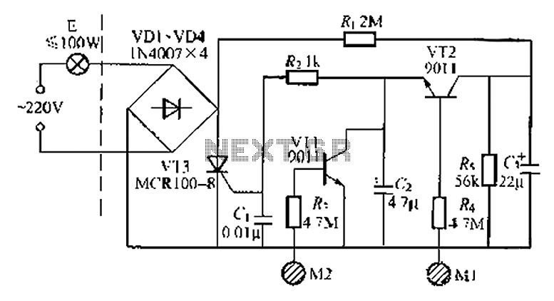
An electronic ballast is a device used to regulate the current to fluorescent lamps and provide sufficient voltage to start the lamps. The design of a transistor-based electronic ballast for a 40W, 230V fluorescent lamp involves several critical steps, including component selection, circuit design, and implementation.
1. **Component Selection**: The first step in designing an electronic ballast is selecting appropriate components. Key components include:
- **Transistors**: Power MOSFETs or IGBTs are typically used for switching. The choice depends on the desired efficiency and switching speed.
- **Inductor**: An inductor is used to limit the current and provide the necessary ballast function.
- **Capacitors**: These are used for filtering and stabilizing the voltage.
- **Diodes**: Fast recovery diodes may be included for rectification purposes.
- **Resistors**: Used for current sensing and feedback control.
2. **Circuit Design**: The circuit design process involves creating a schematic that integrates the selected components. The following elements should be included:
- **Input Stage**: This stage includes a rectifier circuit to convert the AC voltage (230V) to a suitable DC voltage for the transistors.
- **Oscillator Circuit**: A high-frequency oscillator is required to drive the transistors. This can be achieved using a feedback loop to ensure stable operation.
- **Output Stage**: The output stage includes the inductor and capacitors, which work together to provide the necessary voltage and current to the fluorescent lamp.
3. **Simulation**: Prior to physical implementation, the circuit should be simulated using electronic design automation (EDA) software. This step helps in verifying the functionality of the circuit and allows for adjustments to be made before actual construction.
4. **Prototype Development**: After successful simulation, a prototype of the electronic ballast can be built on a breadboard or PCB. This prototype should be tested for performance under various conditions to ensure reliability and efficiency.
5. **Testing and Optimization**: The final step involves rigorous testing of the prototype. Measurements should be taken for input current, output voltage, and the operating frequency. Adjustments may be necessary to optimize performance and ensure compliance with safety standards.
The design of a transistor-based electronic ballast for a 40W, 230V fluorescent lamp requires careful consideration of each component and stage to ensure efficient and reliable operation.I need a circuit diagram for electronic ballast (40w,230v) transistor based circuit diagram. What are the steps taken to design a electronic ballast?.. 🔗 External reference
Related Circuits
The fishing circuit, as illustrated in figure 11-6, comprises a timing circuit and an audio circuit. The components 555, RP1, and C1 form the single-shot circuit, with the defined time calculated as td = 1.1RP1C1. The maximum defined time...
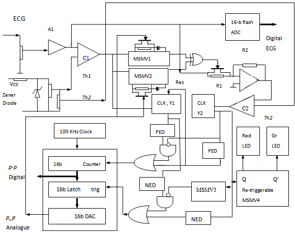
The p-Wave Locked Loop (PWLL) provides an instantaneous measurement of the p to p time interval of the applied electrocardiogram (ECG) signal, facilitating heart rate variability studies based on p-p variations. The initial version of the PWLL began by...
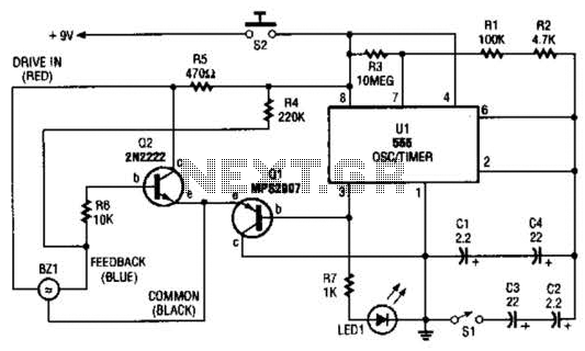
The electronic darkroom timer is constructed using a 555 oscillator/timer, a pair of general-purpose transistors, a buzzer, and an LED. The 555 timer (U1) is set up as an astable multivibrator, functioning as a free-running oscillator. The frequency of...
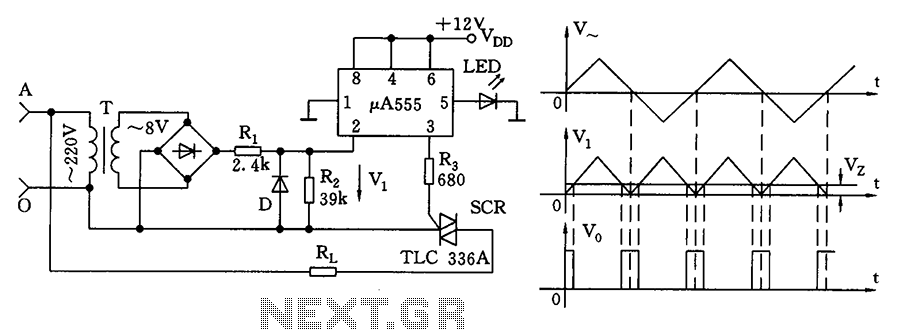
The zero volt switching circuit generates a trigger pulse at the zero crossing of the AC voltage. To facilitate this, the zero crossing of the 555 limit comparator is connected to a single form, with the comparison voltage set...
A good performance is achieved with a two-wire connection for a double touch switch that can function even if there is a break in the left part of the line. This switch is designed for general lighting control, such...
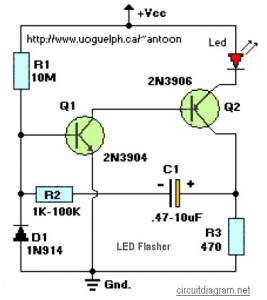
This circuit is designed to flash a high-brightness red LED (5000 mcd), making it suitable for use in fake car alarms or other devices intended to attract attention. The specific values of the components are not critical, allowing for...