
Darkroom Timer Circuit

This high output is applied to the base of transistor Q1 (an MPS2907 general-purpose PNP device), keeping it in the off state. The high output is also directed to the anode of LED1 (used as a power-on indicator) through resistor R7, causing it to illuminate. Timing capacitors C1 through C5 begin to charge through timing resistors R1 through R3. A DC voltage is supplied to the driver input of buzzer BZ1 through resistor R5 and to its feedback terminal via resistor R4, which is also connected to the base of transistor Q2. The positive voltage applied to the base of Q2 turns it on, tying the common terminal of BZ1 high. Once the timing capacitors are adequately charged, a trigger pulse is sent to pin 2 (the trigger input) of U2, resulting in a momentary low output from U1. This causes LED1 to turn off and transistor Q1 to turn on, grounding the common lead of buzzer BZ1, which then produces sound. Subsequently, the output of U1 returns to a high state, turning off Q1 and illuminating LED1 again, repeating the cycle upon the next time interval. The circuit is powered by a 9-V AC adapter, which connects to a standard 117-V household outlet. Due to the circuit's low current draw of approximately 10 to 15 mA, it can also be powered by a 9-V alkaline battery typically used in transistor radios.
The electronic darkroom timer is designed to provide precise timing for photographic development processes. The 555 timer operates in an astable mode, generating a continuous square wave signal that can be easily adjusted by changing the resistor and capacitor values in the timing network. The use of switch S1 allows for user-friendly adjustments to the timing intervals, making the device versatile for various darkroom applications.
The choice of transistors (Q1 and Q2) ensures reliable switching capabilities, allowing the circuit to control the buzzer and LED effectively. The buzzer serves as an audible indicator of the timing intervals, while the LED provides a visual cue for the operational status of the circuit. The circuit's design accommodates both AC and battery power sources, enhancing its portability and usability in different environments.
In summary, this electronic darkroom timer circuit combines simplicity with functionality, making it an essential tool for photographers requiring precise timing during the development of photographic materials. Its design is robust yet straightforward, suitable for both hobbyists and professionals in the field. The electronic darkroom timer is built around a 555 oscillator/timer, a pair of general-purpose transistors, a buzzer, and an LED. The 555 (Ul) is configured as an astable multivibrator (free-running oscillator). The frequency of the oscillator is determined by the values through i3 and Cl through C4. Switch SI is used to divide the capacitor network to vary the time interval between beeps; when SI is closed, the circuit beeps at intervals of 30 seconds.
With SI closed, it beeps at 15-second intervals. When power is applied to the circuit (by closing switch S2), the output of Ul at pin 3 is initially high. That high is applied to the base of transistor Ql (an MPS2907 general-purpose pnp device), keeping it turned off. That high is also applied to the anode of LED 1 (which is used as a power on indicator) through resistor~R7, turning it on.
Timing capacitors Cl through C5 begin to charge through timing resistors Rl through R3. dc voltage is applied to BZl`s driver input through R5 and to its feedback terminal (through R4), which is also connected to Q2`s base terminal. The V+ voltage that applied to Q2`s base causes it to turn on, tying BZl`s common terminal high. When the timing capacitors are sufficiently charged, a trigger pulse is applied to pin 2 (the trigger input) of U2, causing Ul`s output to momentarily go low.
This causes LED1 to go out and transistor Ql to turn on. That, in turn, grounds the common lead of buzzer BZ1, causing BZ1 to sound. Afterward, the output of Ul returns to the high state, turning off Ql, and turning on LED1, until another time interval has elapsed and the process is repeated. The circuit is powered by a 9-Vac adapter, which plugs into a standard 117-V household outlet. Because the circuit draws only about 10 to 15 mA, a 9-V alkaline transistor-radio-battery can also be used to power the circuit.
Related Circuits
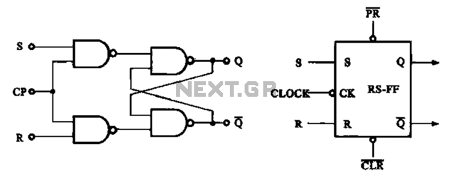
The asynchronous RS flip-flop mentioned earlier is not synchronized with the system clock signal. In contrast, the synchronous RS flip-flop incorporates synchronization, allowing it to operate in conjunction with the clock signal. Figure (a) illustrates the circuit configuration of...
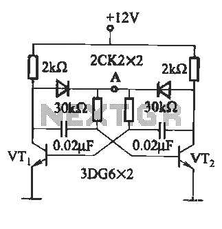
The circuit illustrated in Figure (A) consists of resistors R1 and R2 with values ranging from 15 to 18 kΩ, and capacitors C1 and C2 with capacitance values between 0.01 µF and 10 µF. Figure (B) depicts the oscillation...

To create a PWM controller, begin with a sawtooth generator powered by a 7.5V regulated supply to achieve a Vpp of 5V. Connect the sawtooth output to one input of a comparator and the MAP voltage to the other...
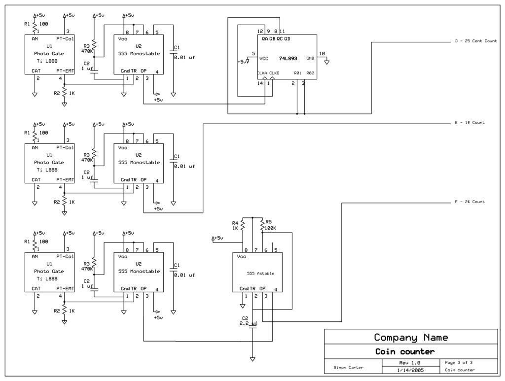
The next counter section operates similarly but is designed to count four quarters, single $1 coins (loonies), and single $2 coins (toonies). The circuit for the toonies is configured. The circuit for the counter section includes a digital counting mechanism...
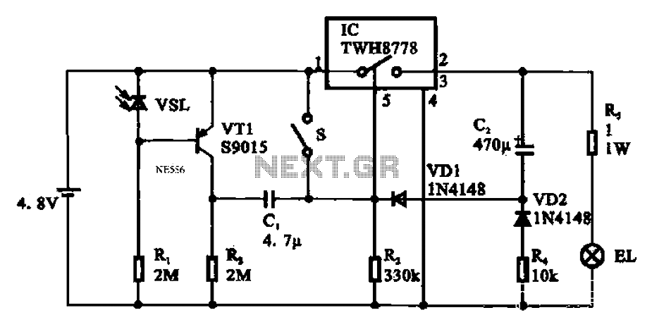
Automatic emergency lamp circuit featuring an electronic switch integrated circuit. This circuit is designed for automatic emergency lighting. The system operates based on ambient light conditions; when light levels are low at night, the circuit activates the emergency lamp....
The electric thermos temperature detection control circuit is designed to monitor and manage the temperature within an electric thermos. It primarily consists of a control circuit for the boiler heater and heater insulation, an electrical magnetic pump motor drive...