
Band 2 Preamplifier

The described circuit employs two 2N3819 field-effect transistors (FETs) arranged in a cascode configuration, which is advantageous for enhancing gain and bandwidth in high-frequency applications. The lower FET, operating in common source mode, serves as the primary amplifying element, providing a significant voltage gain. This configuration allows for improved input and output impedance characteristics, which is essential for maintaining signal integrity.
The upper FET, functioning in common gate mode, contributes to the overall gain while also providing isolation between the input and output stages. This arrangement minimizes the Miller effect, thus allowing for higher frequency operation without significant degradation of performance. The cascode configuration is particularly effective in RF applications, where maintaining signal fidelity over a range of frequencies is critical.
The tunability of the lower FET is a key feature, enabling the adjustment of the circuit for optimal performance at a desired frequency, which is particularly useful in applications such as radio receivers where precise tuning to specific station frequencies is required. The circuit design should also include appropriate biasing networks to ensure that both FETs operate in their linear regions, thus maximizing the efficiency and linearity of the amplifier.
In addition, careful selection of passive components, such as resistors and capacitors, is necessary to tailor the frequency response and stability of the circuit. The coil details mentioned will likely specify the inductance values and winding configurations that complement the FETs' characteristics, further enhancing the circuit's performance in its intended application. Overall, this circuit design exemplifies a sophisticated approach to high-frequency amplification using FET technology.The circuit uses two 2N3819 FET`s in cascode configuration. The lower FET operates in common source mode, while the upper FET, operates in common gate, realising full high frequency gain. The bottom FET is tunable allowing a peak for a particular station. Coil details follow: 🔗 External reference
Related Circuits
This notch filter operates at frequencies up to 200 kHz and utilizes a modified Wien bridge to select the center frequency. The PI component determines the notch bandwidth, which defines the range of frequencies that are attenuated. The notch...
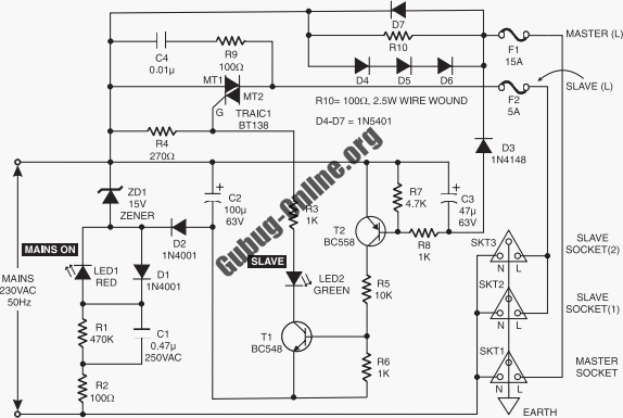
This circuit design features a modular arrangement that enables users to select only the modules best suited to their needs, allowing for the construction of a chain ranging from one to five modules in length. For those seeking a...
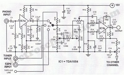
This Hi-Fi stereo preamplifier circuit is constructed using the TDA1054 integrated circuit (IC) from SGS. The TDA1054 is housed in a 16-pin DIL package and incorporates two separate preamplifier circuits. It is characterized by low noise and minimal issues...
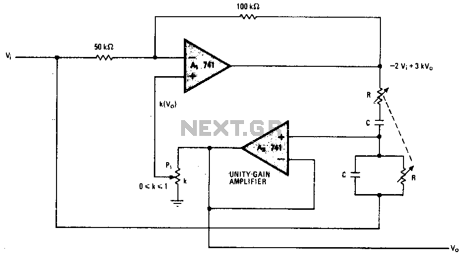
Figure (a) illustrates a general inverting amplifier circuit, which includes a 100k potentiometer as a feedback resistor connected in series between the input terminal and the inverting input to compensate for the DC bias current. The potentiometer (Rp) should...
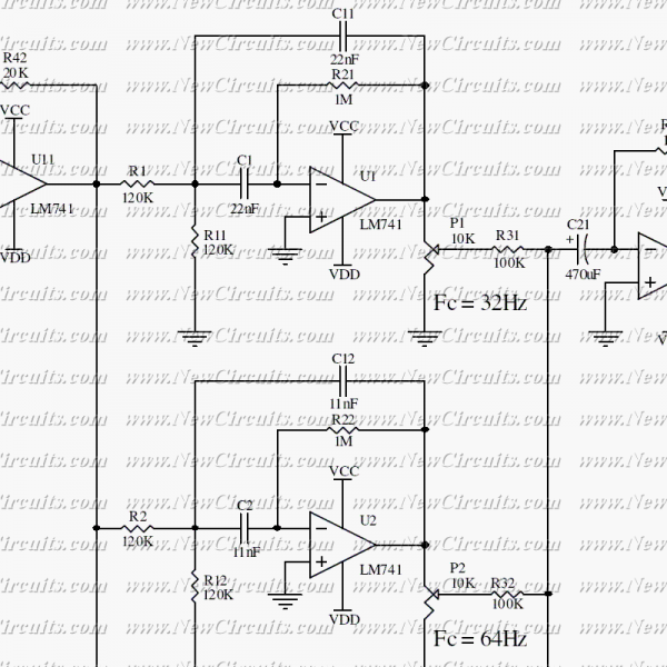
This circuit allows you to equalize the audio signals in ten bands. It uses low-cost op-amps to form a professional equalizer circuit. The heart of the design is a classical band-pass active filter. The U11 acts as an attenuator...
The circuit is fundamentally based on a well-tested simple microphone preamplifier design. A prototype of this circuit has been constructed and has demonstrated effective performance. The Sound Blaster soundcard series (SB16, SB32, AWE32, and AWE64) features a microphone input...