
Band 2 Preamplifier

The described circuit employs a configuration of two Field Effect Transistors (FETs) to achieve enhanced amplification characteristics suitable for high-frequency applications. The lower FET, configured in common source mode, is responsible for providing voltage gain. This configuration is known for its ability to amplify small signals while maintaining a relatively high input impedance and low output impedance, which is advantageous for interfacing with other circuit stages.
In contrast, the upper FET is configured in common gate mode. This configuration is particularly effective for high-frequency applications as it offers a low input capacitance and high bandwidth. The common gate arrangement allows for improved stability and linearity, making it suitable for RF amplification. The combination of the common source and common gate configurations in a single circuit allows for a broad frequency response and high overall gain.
The tunability of the lower FET is a critical feature, as it enables the circuit to be adjusted for optimal performance at a specific frequency, such as that of a targeted radio station. This tunability can be achieved through the use of a variable resistor or capacitor in conjunction with the FET, allowing for fine-tuning of the gain characteristics and frequency response.
Coil details, which are essential for determining the resonant frequency and impedance matching of the circuit, would typically include specifications such as inductance, Q factor, and physical dimensions. These parameters will play a significant role in the overall performance of the circuit, particularly in tuning and frequency selectivity.
Overall, this circuit design exemplifies a sophisticated approach to high-frequency amplification, leveraging the unique properties of FETs in different configurations to achieve desired performance metrics. The integration of tunable components further enhances the versatility and functionality of the circuit in practical applications.The lower FET operates in common source mode, while the upper FET, operates in common gate, realising full high frequency gain. The bottom FET is tunable allowing a peak for a particular station. Coil details follow: 🔗 External reference
Related Circuits
The original description discusses an application that is reputed for its high-quality sound. This superior sound quality is attributed to the operation of the entrance transistors at Class A. The sound quality is largely dependent on IC1, which needs to...
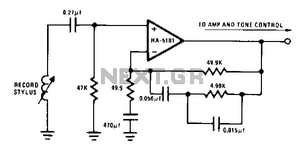
The circuit provides low-frequency boost below 318 Hz and high-frequency attenuation above 3150 Hz. Recent modifications to the response standard include a 31.5-Hz peak gain region to reduce de-oriented distortion from external vibration. The described circuit functions as an audio...

Frequency shift keying (FSK) is a widely used digital modulation technique for data transmission. Common applications of FSK modulation encompass both wired and wireless data transmission, as well as infrared remote controls for consumer electronic devices. FSK demodulation can...
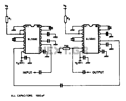
A wideband high gain configuration using two SL550s connected in series. The first stage is connected in a common emitter configuration, while the second stage is a common base circuit. Stable gains of up to 65 dB can be...
I wanted a robust, portable, compact antenna usable for horizontal and vertical polarisation to take along with my FT-817 when I go on vacation, camping etc. I also wanted the dipole to cover the VHF and UHF bands and...
Here is a nice little receiver for narrow-band FM reception. It can also be used to receive FSK, RTTY and PACKET signals from the HF bands. Basic receiver sensitivity is in the region of 1uV PD and the receiver...