
VHF - UHF band reciever

Due to the choice of IF, the wanted and image frequencies are only 910KHz away from each other. This means that with just one tuned circuit in the antenna circuit the image rejection will be poor for frequencies above about 20MHz. I thought that doesn't worry me because there are fewer stations above 20MHz to worry about. Image rejection is quite reasonable on the prototype at 14.1MHz but there was almost no image rejection at 100.455KHz. If you want a better image rejection at HF then I suggest you add another tuned circuit in the antenna circuit. Consider a converter circuit if you want to receive VHF or UHF bands above 100MHz. There is a section of "blob-board" on the PCB that can be used to build. This board is intended to be used in a variety of applications so the complete receiver becomes a building-block that may be used to make:
An AF amplifier + squelch circuit for speech. An R/C decoder for the control of models. RTTY / PACKET FSK to RS232 driver (no modem needed). Tone decoder for signalling applications. (insert another clever use of your own here) I will post a few practical circuits later for some of the above applications, but my first task is an FSK to RS232 driver (Baycom compatible) so I can have a direct link to my brother G0TLA in England. This uses just two x 741 Op-Amps, one to generate -8v from the battery, the other to give +/- 8-volts signalling for feeding pin-3 of a serial COM port of the computer. I tried to add an RF amplifier but it wasn't needed; the RF sensitivity is about 1uV PD without it. I have added the PCB foil to the DOWNLOAD section together with the component overlay. In the component overlay all tuned windings are marked "P" and link input/outputs are marked "S". The approximate coil winding ratios are given beside T1 and T2 in the circuit diagram. T1 and T2 I wound on IF transformers from AES (part No: IL-100 at US$0.95 for a pack of five). In the prototype, T1 and T2 are wound according to the following table:
Frequency Coil Primary Tapping Secondary Cy 13-19MHz T1 11-turns 1-turn 3-turns 33pf 13-19MHz T2 11-turns none 2 turns 33pf 19-27MHz T1 11-turns 1-turn 3-turns 15pf 19-27MHz T2 11-turns none 1-turn 15pf 26-35MHz T1 11-turns 1-turn 3-turns 8.2pf 26-35MHz T2 11-turns none 1-turn 8.2pf 33-43MHz T1 7-turns 1-turn 2-turns 6.8pf 33-43MHz T2 7-turns none 1-turn 6.8pf 100MHz T1 4-turns 1-turn 2-turns 5.6pf 100MHz T2 4-turns none 1-turn 5.6pf For 100MHz the internal ferrite is removed from the can. T3 and T4 are standard 455KHz IF cans from AES. Cx is contained in the IF transformers. Use the YELLOW cans for T3 and T4 but the other cans you can strip down and rewind for T1 and T2. The pads on the PCB will accommodate both the pin-out variations found in these packs. Note that one of the cans in this pack has a 180pf capacitor mounted horizontally flat between the coil and base. The former will have to be super-glued back to the base after removal of the capacitor. Note also that T4 secondary is not used.
The described receiver is a versatile narrow-band FM receiver capable of handling various digital modes such as FSK, RTTY, and PACKET signals across HF bands. The design features a single-sided PCB layout, which is atypical for such circuits, allowing for compact assembly while maintaining functionality. The receiver's sensitivity of approximately 1µV PD ensures effective operation even in weak signal environments, making it suitable for applications in amateur radio and other communications where low signal levels are common.
The RF transformers, T1 and T2, are critical components in determining the operational frequency range of the receiver. The selection of these transformers, along with the tuning capacitor (Cy), is essential for optimizing performance across the desired frequency bands. The specified winding configurations for different frequency ranges illustrate the adaptability of the design to various applications, such as CB, 10-meter, and radio control bands.
The oscillator stage employs a harmonic oscillator configuration, providing flexibility in frequency selection by allowing for crystal oscillation or VFO operation, albeit with trade-offs in frequency stability. The integration of a dual-gate FET for mixing and a ceramic filter (CFK455) for IF processing enables effective signal demodulation and amplification, culminating in audio frequency output via the TBA120 chip.
Furthermore, the design addresses image frequency rejection challenges by suggesting additional tuned circuits for improved performance at higher frequencies. The inclusion of a "blob-board" section on the PCB enhances the receiver's versatility, enabling users to implement various additional circuits, such as AF amplifiers, decoders, and tone detection applications.
The receiver's layout accommodates standard components, ensuring ease of assembly and modification. The detailed specifications for transformer windings provide essential guidance for builders, while the option to utilize standard IF cans simplifies sourcing components. Overall, this receiver design represents a practical solution for hobbyists and engineers interested in exploring narrow-band FM and digital communication techniques.Here is a nice little receiver for narrow-band FM reception. It can also be used to receive FSK, RTTY and PACKET signals from the HF bands. Basic receiver sensitivity is in the region of 1uV PD and the receiver can be tuned to almost any frequency from 100KHz up to probably 120MHz. It is a bit big and cramped, but I think you will have no difficulties reading it. The receiver is built on a single- sided PCB, which is quite unusual for this type of circuit. I do have a PCB available, but more about that later. The RF transformers T1 & T2 and the capacitor Cy are chosen for the frequency you are interested in. As an example, using re-wound IF transformers (from Antique Electronic Supply, Tempe) the former is about 3.5mm Dia.
and 10 turns (thin wire) plus Cy=33pf tuned 26MHz to 35MHz. This covers CB, 10-meters and the radio control bands. Although the circuit looks quite complex it is really very simple. The first transistor is a harmonic oscillator so arranged that it will oscillate at any valid harmonic of the crystal. Replacing the crystal with a capcitor will result in VFO operation but the frequency stability is not so good.
The oscillator and antenna tuned circuit, T2, are fed into a dual-gate FET where mixing takes place and produces the 455KHz IF. This is filtered by the CFK455 ceramic filter, amplified by the next two transistors and presented to the TBA120 (pins 13 & 14) which does all the rest.
It delivers AF from the output, pin 8. Without the 10uf output capacitor you can see a DC shift corresponding to the frequency shift of the input signal. All NPN transistors can be replaced with almost any NPN transistor, such as the 2N2222 etc. Due to the choice of IF, the wanted and image frequencies are only 910KHz away from each other. This means that with just one tuned circuit in the antenna circuit the image rejection will be poor for frequencies above about 20MHz.
I thought that doesn't worry me because there are fewer stations above 20MHz to worry about. Image rejection is quite reasonable on the prototype at 14.1MHz but there was almost no image rejection at 100.455KHz. If you want a better image rejection at HF then I suggest you add another tuned circuit in the antenna circuit.
Consider a converter circuit if you want to receive VHF or UHF bands above 100MHz. There is a section of "blob-board" on the PCB that can be used to build. This board is intended to be used in a variety of applications so the complete receiver becomes a building- block that may be used to make: An AF amplifer + squelch circuit for speech. An R/C decoder for the control of models. RTTY / PACKET FSK to RS232 driver (no modem needed). Tone decoder for signalling applications. (insert another clever use of your own here) I will post a few practical circuits later for some of the above applications, but my first task is an FSK to RS232 driver (Baycom compatible) so I can have a direct link to my brother G0TLA in England.
This uses just two x 741 Op-Amps, one to generate -8v from the battery, the other to give +/- 8-volts signalling for feeding pin-3 of a serial COM port of the computer. I tried to add an RF amplifer but it wasn't needed; the RF sensitivity is about 1uV PD without it. I have added the PCB foil to the DOWNLOAD section together with the component overlay. In the component overlay all tuned windings are marked "P" and link input/outputs are marked "S". The approximate coil winding ratio's are given beside T1 and T2 in the circuit diagram. T1 and T2 I wound on IF transformers from AES (part No: IL-100 at US$0.95 for a pack of five). In the prototype, T1 and T2 are wound according to the following table: Frequency Coil Primary Tapping Secondary Cy 13-19MHz T1 11-turns 1-turn 3-turns 33pf 13-19MHz T2 11-turns none 2 turns 33pf 19-27MHz T1 11-turns 1-turn 3-turns 15pf 19-27MHz T2 11-turns none 1-turn 15pf 26-35MHz T1 11-turns 1-turn 3-turns 8.2pf 26-35MHz T2 11-turns none 1-turn 8.2pf 33-43MHz T1 7-turns 1-turn 2-turns 6.8pf 33-43MHz T2 7-turns none 1-turn 6.8pf 100MHz T1 4-turns 1-turn 2-turns 5.6pf 100MHz T2 4-turns none 1-turn 5.6pf For 100MHz the internal ferrite is removed from the can.
T3 and T4 are standard 455KHz IF cans from AES. Cx is contained in the IF transformers. Use the YELLOW cans for T3 and T4 but the other cans you can strip down and rewind for T1 and T2. The pads on the PCB will accomodate both the pin-out variations found in these packs. Note that one of the cans in this pack have a 180pf capacitor mounted horisontally flat between the coil and base. The former will have to be super-glued back to the base after removal of the capacitor. Note also that T4 secondary is not used. 🔗 External reference
Related Circuits
The following segment provides the enhanced Motorola schematic for a typical application of the MRF141G, which includes parasitic stabilization features. The MRF141G is a broadband power RF MOSFET capable of delivering a conservatively rated 300 watts across the FM...
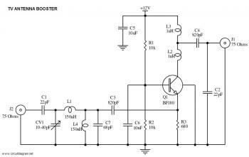
This is a straightforward circuit for a UHF band TV antenna booster that provides a gain of 15 dB. This low-cost antenna booster is simple and easy to construct. The UHF band TV antenna booster circuit is designed to enhance...
When the start switch is pushed, the output of the charger goes to 14.5 V. As the battery approaches full charge, the charging current decreases and the output voltage is reduced from 14.5V to about 12.5V, terminating the charging...
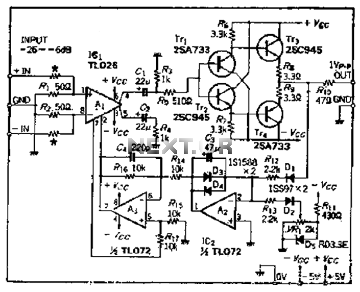
A car circuit is utilized for external voltage-controlled amplification in wideband amplifiers using the TL0216 IC. This design incorporates compression characteristics of 2dB. The input circuit consists of resistors that reduce the input level when it is between -26dB...

This circuit is designed for a UHF TV antenna and provides a 15 dB preamplification. It is constructed using a transistor and minimal components. The schematic features the BF180 UHF transistor. The first stage consists of a band-pass filter...
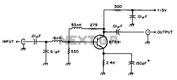
The amplifier delivers a gain of 10 dB across a frequency range of 10-600 MHz and features a 1-to-1 impedance match at 50 ohms. The BFR91 transistor exhibits a noise figure of 1 dB at 500 MHz. The circuit...