
Basic 2051`s Circuit

The circuit described utilizes the 89C2051 microcontroller, which is a member of the 8051 family of microcontrollers. This microcontroller is commonly used in embedded applications due to its versatility and ease of integration. The circuit is designed for simplicity, employing point-to-point soldering techniques on a universal printed circuit board (PCB), which allows for flexibility in layout and component placement.
The microcontroller is seated in a standard 20-pin dual in-line package (DIP) socket, which facilitates easy replacement and connection. It is important to note that a circle-pin socket should not be used, as it may not provide reliable connections for the microcontroller's pins.
In the circuit, D1 is represented as a small dot LED, which serves as a visual indicator for the circuit's operational status. The LED's anode is typically connected to a positive voltage, while the cathode is connected to a current-limiting resistor that ensures proper current flow and prevents damage to the LED.
Power regulation is handled by U2, which can be either a 7805 voltage regulator or a 78L05. Both of these components are linear voltage regulators that provide a stable +5V output, suitable for powering the 89C2051 microcontroller and other peripheral components. The choice between the two depends on the current requirements of the circuit, with the 78L05 being suitable for lower current applications.
An optional component, U3, is included in the design to correct any polarity issues that may arise from the DC power adapter. This feature is particularly useful in preventing damage to the microcontroller and associated components if the power supply is connected with reverse polarity.
Before inserting the 89C2051 microcontroller into the socket, it is crucial to verify the integrity of the connections. This can be done by measuring the voltage between pin 20 (Vcc) and pin 10 (GND) of the socket, ensuring that a +5V supply is present. This step is essential to confirm that the power supply is functioning correctly.
To test the LED functionality, a simple procedure involves shorting the P1.7 pin to ground (GND). This action should illuminate the LED, indicating that the microcontroller's output pin is functioning as intended. This testing method is a straightforward way to ensure that the circuit is correctly assembled and operational before proceeding with further development or programming of the microcontroller.A basic circuit of the 89C2051 shown here can be made easily using point-to-point soldering with a universal PCB. Use an ordinary 20-pin socket, do not use a circle-pin socket. D1 is a small dot LED. U2 can be either 7805 or 78L05. U3 is optional for correcting any polarity DC adapter. Without the 2051 chip in the socket, checks the connection, then measures +5V between pin 20 and pin 10. Test the LED by shorting P1.7 pin to GND. 🔗 External reference
Related Circuits
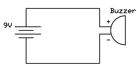
This project involves connecting the positive terminal of the battery to the positive lead of the buzzer and the negative terminal of the battery to the negative lead of the buzzer. Typically, the positive lead of the buzzer is...
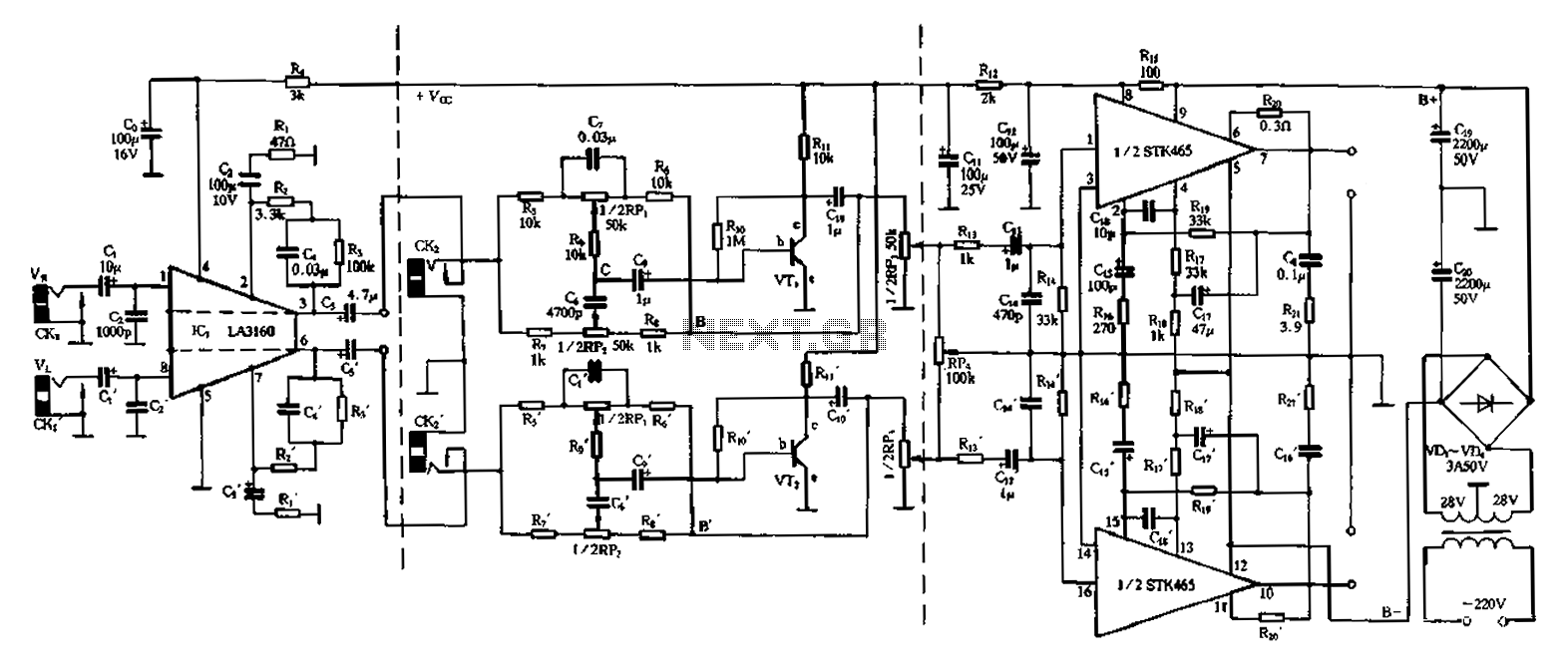
The 50W is a two-channel amplifier featuring a preamplifier and tone control based on the LA3160 integrated circuit. Its external components include the input preamplifier, with C1 serving as the input coupling capacitor. The circuit incorporates a high-frequency bypass...
This circuit describes a simple 6-bit random number pseudo-generator used to study binary counters and, in particular, shift registers. Some basic background information about binary counters and shift registers is provided. In reality, there are dozens of different shift...

A single operational amplifier, one of four included in the widely used LM324, is functioning within a variable pulse-width, free-running square wave oscillator circuit. Its output drives two transistors that manage the on/off cycle of the tape-drive motor. The...

This circuit is a low-noise preamplifier designed for the 435-MHz amateur satellite frequencies. It utilizes a Mitsubishi MGF1302 transistor. A 28-Vdc power source is indicated; however, lower voltages can be employed by adjusting the 400-5-W resistor. The low-noise preamplifier circuit...

This circuit represents a remote control unit that utilizes radio frequency signals to operate various electrical appliances. The remote control unit features four channels, which can be expanded to twelve. This circuit stands out from similar designs due to...