
Basic Circuit Modification of Kodak Disposable Camera

The Kodak MAX Flash Unit circuit is designed to provide a reliable power source for flash photography, utilizing a combination of capacitors, resistors, and semiconductors to achieve optimal performance. The core of the circuit typically includes a high-voltage capacitor that stores energy, which is then rapidly discharged to power the flash bulb when triggered.
Key components in the circuit may include:
1. **Capacitor**: A high-voltage capacitor is essential for storing charge. The capacitance value determines the amount of energy that can be stored, affecting the brightness and duration of the flash.
2. **Transistor**: The circuit may utilize a transistor as a switch to control the discharge of the capacitor. When the flash is activated, the transistor allows current to flow, discharging the capacitor through the flash bulb.
3. **Resistors**: Various resistors in the circuit help to control the current flow and protect sensitive components from excessive voltage.
4. **Diodes**: Diodes may be incorporated to prevent back EMF from damaging other components when the flash discharges.
5. **Trigger Mechanism**: A trigger circuit is often included, which can be activated by a button or a signal from a camera. This mechanism ensures that the flash fires at the correct moment.
The layout of the circuit is critical for ensuring efficient operation. Components should be arranged to minimize the length of connections, reducing the risk of inductance and ensuring quicker response times. Proper insulation and spacing between high-voltage components must also be maintained to prevent arcing and ensure safety.
In summary, the Kodak MAX Flash Unit circuit design effectively combines various electronic components to deliver a powerful flash for photography, while the provided circuit diagram serves as a guide for both understanding and modifying the unit as needed. Following the outlined disassembly and reconstruction steps will aid in successfully completing this project.The circuit diagram shows the original Kodax MAX Flash Unit including the semiconductors that built the circuit. The shown circuit diagram is the unmodified one which is for the regular Kodak and the Kodak Max that should be very similar if not identical.
See materials and tools needed, how to disassembly and then rebuilt the modification one to b e a completed project. 🔗 External reference
Related Circuits
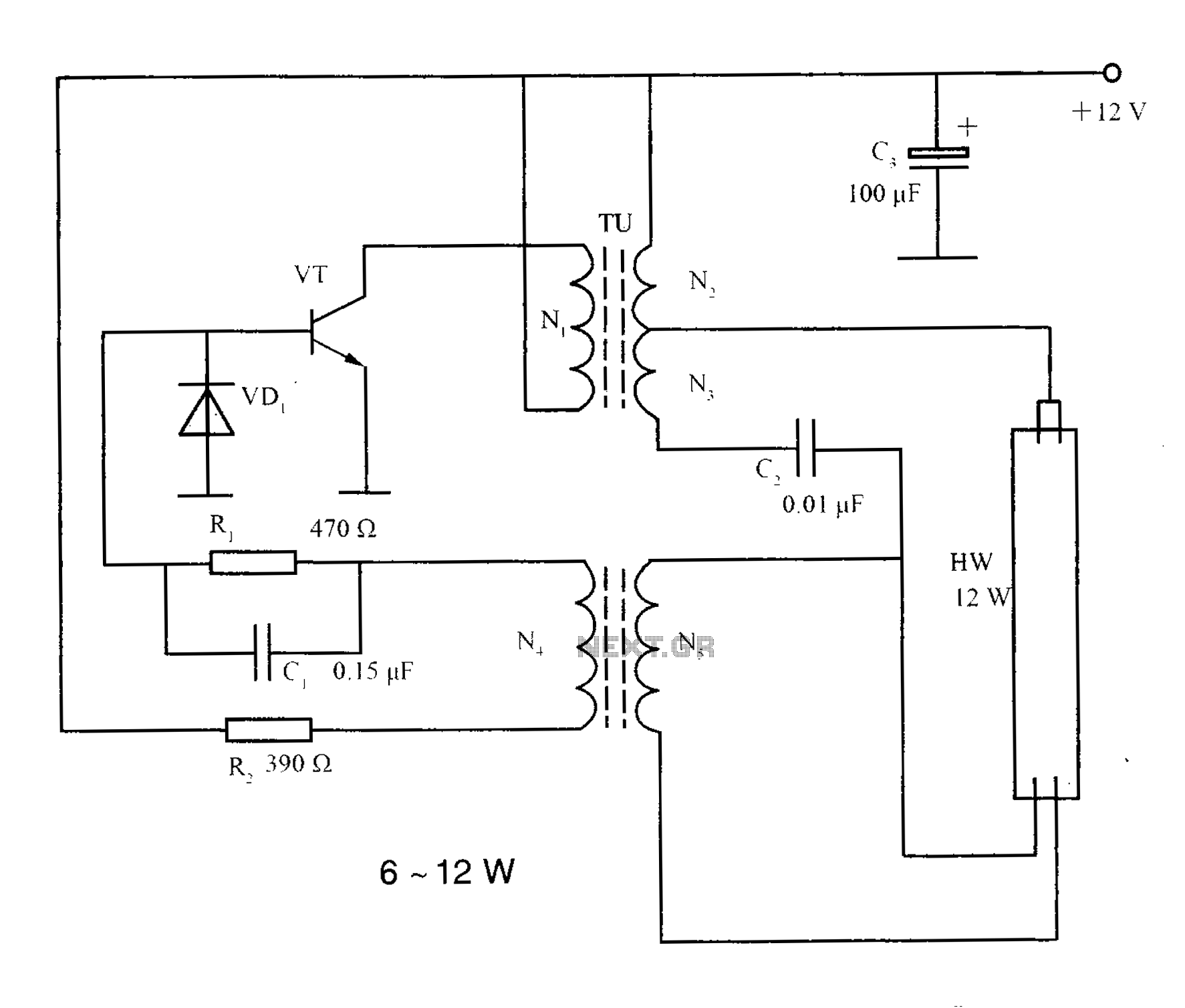
The lighting inverter circuit is designed for 6 to 12W fluorescent lamps. It operates by first bucking the mains voltage, followed by rectification and filtering to charge a battery. When the inverter is activated, it generates a high-frequency alternating...
Typical segment display LEDs consume around 25 mA for each segment and should be limited to this current with resistors. For a six-digit display to be current limited, at least 42 series resistors are needed. The brightness of the...
Adding a discharge path to the upper MOSFET of a cascode circuit significantly reduces the unavoidable Miller effect, thereby enhancing the Power Factor Correction (PFC) performance of a power supply's front end. In a cascode configuration, the upper MOSFET is...
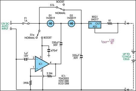
This circuit is designed to charge between one and twelve NiCd cells using a car battery. When switch S1 is in the "normal" position, it can charge up to six cells. The LM317 regulator functions as a simple current...

Circuit characteristics: A simple phase shift range of 180 degrees, with a practical range of 170 degrees. The circuit is influenced by temperature and is suitable for small power applications in less demanding situations. The circuit operates by utilizing a...
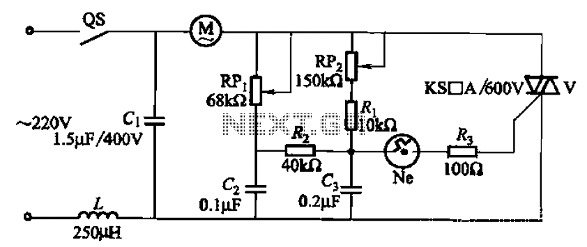
The 3P10 circuit, illustrated in the figure, utilizes a bidirectional thyristor for control. The adjustment potentiometer RPi allows for modification of the minimum motor speed, while the adjustment potentiometer RP2 enables continuous variation of the motor speed, reaching up...