
One variable speed single-phase motor circuit thyristor

The 3P10 circuit is designed to control the speed of a motor through the use of a bidirectional thyristor, which provides efficient switching capabilities for AC loads. The circuit includes two potentiometers: RPi, which sets the minimum speed of the motor, and RP2, which allows for fine-tuning of the speed across a continuous range. This configuration enables the user to achieve precise control over the motor's operational speed, facilitating applications that require variable speed operation.
The pressure range of 30 to 215V indicates the operational voltage limits within which the circuit can function effectively. This range suggests that the circuit is suitable for a variety of AC motors that operate within these voltage parameters. The use of a bidirectional thyristor is advantageous as it can conduct current in both directions, making it ideal for alternating current applications.
In practical implementation, the circuit would typically include additional components such as filtering capacitors to smooth out voltage fluctuations, protection diodes to prevent reverse voltage spikes, and possibly a microcontroller for automated speed adjustments based on feedback from sensors. The design should ensure that the components are rated appropriately for the voltage and current levels expected during operation to ensure reliability and safety.
Overall, the 3P10 circuit represents a robust solution for motor speed control, offering flexibility and precision through its adjustable parameters. Proper attention to component selection and circuit layout will be essential for optimal performance in real-world applications.3P10 circuit shown in FIG. It uses a bidirectional thyristor control. Adjustment potentiometer RPi, can change the minimum motor speed f adjustment RP2, continuously changing t he motor speed, up to the highest speed. Pressure range of about 30 ~ 215V.
Related Circuits
This is a straightforward, cost-effective Hi-Fi quality power amplifier. It can be constructed in five different configurations, as indicated in the table, ranging from 20 W to 80 W RMS. This Hi-Fi quality power amplifier is designed to deliver high...
Generating variable audio frequencies with crystal precision is challenging due to the scarcity of low-frequency quartz crystals, which typically produce a single frequency. While minor adjustments to the frequency of a crystal oscillator can be made using a trimmer...
The high voltage generator depicted in figure 16-18 utilizes the 555 timer IC as its primary component. The oscillating voltage produced is enhanced through a step-up transformer. The astable multivibrator configuration comprises the 555 timer along with resistors R1...
This circuit is designed to dim lights with a maximum capacity of approximately 350 watts. It employs a standard TRIAC circuit configuration, which has been observed to generate minimal heat during operation. It is important to note that this...
The 27MHz crystal oscillator circuit is illustrated in the figure. Resistors R1, R2, and R3 serve as biasing resistors, while capacitor C6 functions as a bypass capacitor. The voltage division circuit consists of capacitors C1, C3, C4, and C2,...
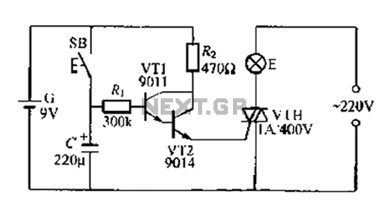
A delay circuit utilizing an electric lamp. Normally, the thyristor VTH remains off, and the lamp E does not illuminate. The lamp turns on when needed, controlled by the FSH, with the VT1 and VT2 components forming a composite...