
Basic Hall Effect Sensor IC

The Hall Effect Sensor operates based on the principle that a voltage is generated across a conductor when it is exposed to a magnetic field perpendicular to the current flow. This phenomenon, known as the Hall Effect, allows for the detection of magnetic fields with high sensitivity and accuracy. Hall Effect Sensors are commonly used in various applications, including automotive systems, industrial automation, and consumer electronics.
The Magnetic Hall Effect Switch, a specific type of Hall Effect Sensor, functions as a binary output device that activates or deactivates based on the presence or absence of a magnetic field. When a magnetic field is applied, the switch closes, allowing current to flow through the circuit. Conversely, when the magnetic field is removed, the switch opens, interrupting the current. This characteristic makes it ideal for applications such as position sensing, speed detection, and contactless switching.
In terms of circuit design, a typical Hall Effect Sensor circuit includes the sensor itself, a power supply, and a load. The sensor is connected to a voltage source, often in the range of 5V to 15V, depending on the specific sensor model. The output can be configured to provide either an analog voltage that varies with the magnetic field strength or a digital output that toggles between high and low states.
To enhance the performance of the Hall Effect Sensor, additional components such as resistors and capacitors may be included in the circuit. Resistors can be used for current limiting and signal conditioning, while capacitors may serve to filter noise and stabilize the output signal. Proper layout and grounding techniques are also crucial to minimize interference and ensure reliable operation.
Overall, the Hall Effect Sensor and Magnetic Hall Effect Switch are essential components in modern electronic systems, providing efficient and reliable methods for magnetic field detection and control.Electronics Tutorial about the Hall Effect Sensor and Magnetic Hall Effect Switch which is an Output Transducer used to detect Magnetic Fields.. 🔗 External reference
Related Circuits
Five pins RA0 to RA4 are used as inputs. The pins are connected to the 5V average resistance 10K (Pull-up). So when no switch is not depressed all the pins have a high potential (HI +5 V). When one...
This two-part article explains the utilization of a simple voltage divider circuit incorporating a thermistor to obtain high-accuracy temperature readings across a wide range of measurements. The first part focuses on the circuit design and explores various methods for...
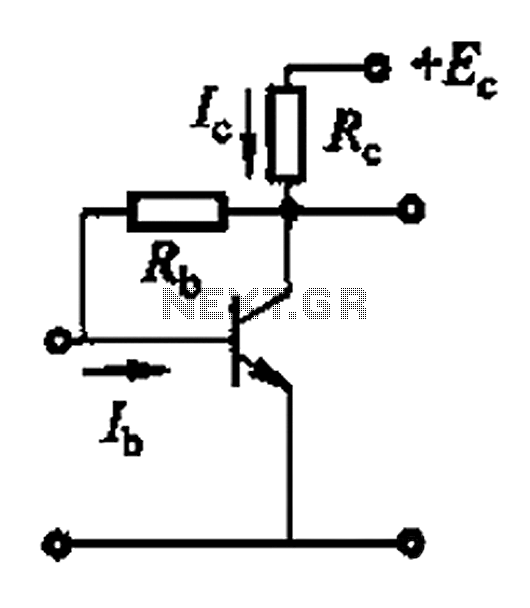
Basic reference bias circuit using a transistor with negative voltage feedback. The basic reference bias circuit utilizing a transistor with negative voltage feedback is designed to provide a stable output voltage or current that is largely independent of variations in...

The Electro Harmonix Big Muff Pi circuit would likely benefit from the incorporation of a modern input-jack power connection and a DPDT bypass switch. The specific types of transistors and diodes used in the circuit are not specified. It...
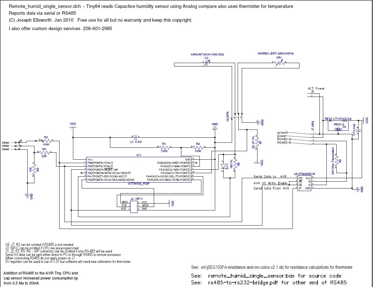
This document explains how to read a capacitive humidity sensor directly from a microcontroller using one resistor, one diode, the sensor, and two I/O lines. This method does not use an ADC but measures the time required to charge...
This is a tutorial for beginners who have recently started learning about electronics. The author has prior experience in programming with C and Python. The schematic presented in this tutorial is designed for novice electronics enthusiasts who are transitioning from...