
Guitar Effect Circuit : Electro Harmonix Big Muff Pi

The Electro Harmonix Big Muff Pi is a renowned distortion and fuzz pedal commonly used in electric guitar applications. The circuit typically consists of multiple stages of gain and clipping, allowing for a wide range of tonal possibilities.
To enhance the performance and usability of the Big Muff Pi, a contemporary input-jack power connection can be integrated. This modification would provide a more reliable power source and potentially improve the overall noise performance of the circuit. The use of a DPDT (Double Pole Double Throw) bypass switch is also advisable. This switch allows for true bypass operation, ensuring that when the effect is disengaged, the signal path remains unaltered, preserving the original tone of the instrument.
While the specific transistors and diodes used in the circuit remain unspecified, it is essential to select high-quality components to maintain the desired sound characteristics. Transistors typically used in fuzz circuits include silicon and germanium types, each contributing distinct tonal qualities. Diodes, often used for clipping, can also significantly affect the sound, with options ranging from standard silicon diodes to more exotic choices like LED or germanium diodes.
In conclusion, implementing a modern input-jack power solution and a DPDT bypass switch, along with carefully selected high-quality transistors and diodes, can enhance the functionality and sound quality of the Electro Harmonix Big Muff Pi circuit, making it more suitable for contemporary use.This Electro Harmonix Big Muff Pi circuit would most likely be better making the change by a contemporary input-jack power and a DPDT bypass switch. The kinds of transistors and diodes are unknown. It really is most likely that any high acq.. 🔗 External reference
Related Circuits
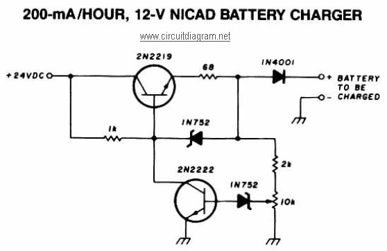
A 12V NiCAD battery charger circuit with a charging rate of 200mA per hour. This circuit initially charges the battery at 75mA until it reaches a full charge, after which the current is reduced to a trickle rate. The...
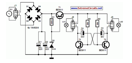
A front wheel with a built-in dynamo was purchased, providing a sine wave output of 30 Vpp at no load. Based on this, a simple power supply was designed using BD911 transistors, which are somewhat oversized for the application,...
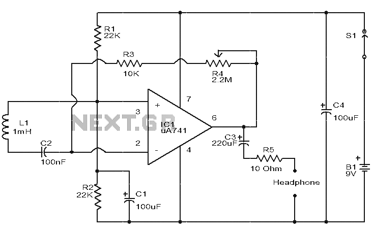
This is a simple circuit designed to detect electromagnetic radiation, including hidden wiring. It utilizes a 1mH inductor to sense the electric field. The induced voltage from the inductor is amplified by an operational amplifier (op-amp). An audio headset...
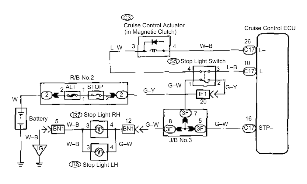
When the brake pedal is depressed, battery positive voltage normally applies through the STOP fuse and stop light switch to terminal STP of the ECU, and the ECU turns the cruise control off. A failsafe function is provided so...

The circuit diagram illustrates a rotation sensor that activates a device, such as a motor or buzzer, when the circuit assembly is rotated. The design is based on the fundamental operation of a 555 timer. The rotation sensor circuit utilizes...

The circuit illustrated in Figure 3-130 differs from the circuit in Figure 3-129 in that when the stop button SB3 is pressed, the electric motor initiates braking. Furthermore, during both the startup and braking phases, the motor power lines...