
Basic multiplier circuits

The Greinacher doubler circuit is a voltage multiplier that utilizes capacitors and diodes to convert an alternating current (AC) input voltage into a higher direct current (DC) output voltage. The basic operation involves charging capacitors during the positive half-cycle of the AC input and discharging them to provide a higher voltage during the negative half-cycle.
In the typical configuration, the circuit consists of two diodes and two capacitors. The first diode allows current to flow into the first capacitor during the positive half-cycle, charging it to the peak voltage (Up). The second diode then conducts during the negative half-cycle, allowing the first capacitor to discharge through the load while simultaneously charging the second capacitor to the same voltage (Up). This results in the output voltage across the load being the sum of the voltages across both capacitors, yielding a total output of 2x Up.
When the input voltage is already symmetrical, as in the case of certain signal sources, the Greinacher doubler can be cascaded to further increase the output voltage. In this configuration, the first doubler's output serves as the input for a second doubler, effectively doubling the output voltage once more. This results in a more complex arrangement of capacitors and diodes, but the fundamental principle remains the same: charging and discharging capacitors through diodes to achieve a higher voltage output.
The Greinacher doubler is widely used in applications where a simple and efficient method of obtaining higher DC voltages from low-voltage AC sources is required, such as in power supplies for electronic devices and in signal processing applications. Its simplicity and effectiveness make it a popular choice in various electronic designs.The Greinacher doubler circuit (a) transforms a grounded AC voltage (peak voltage Up) into symmetrical DC voltages of 1x Up each, thus producing 2x Up between outputs. If the input voltage is already symmetrical (e.g. as in an Obit), the Greinacher circuit may be doubled according to (b). 🔗 External reference
Related Circuits
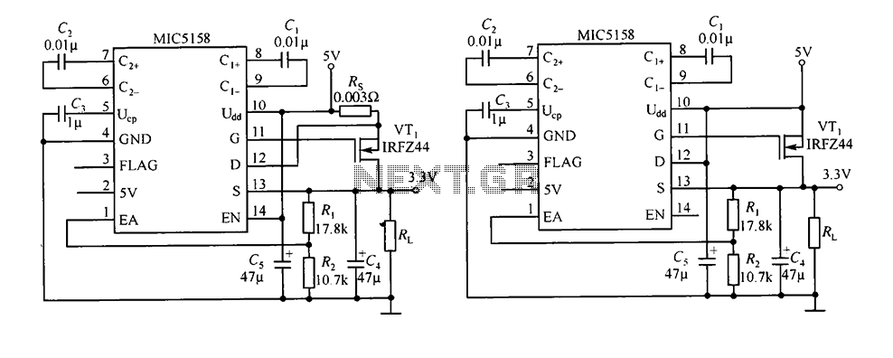
The circuit consists of peripheral components for the MIC5158, a linear regulator that converts a 5V input into a 3.3V output with a maximum current of 10A. When the input voltage (Ui) is 5V, an N-channel MOSFET, specifically the...
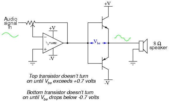
This project is an audio amplifier designed to amplify output signals from small radios, tape players, CD players, or other audio signal sources. For stereo operation, two identical amplifiers must be constructed—one for the left channel and another for...
The circuit below illustrates powering one or two LEDs from the 120-volt AC line using a capacitor to drop the voltage and a small resistor to limit the inrush current. Since the capacitor must pass current in both directions,...
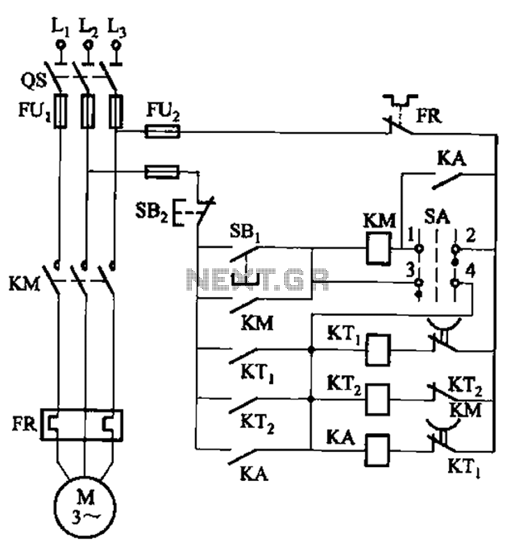
The circuit illustrated in Figure 3-78 utilizes two relays for automatic control, featuring a more complex line structure. This configuration allows for intermittent motor operation. Additionally, it can operate continuously when switch SA is positioned to the right. The circuit...
A 6V to 12V DC converter circuit is designed to convert a lower voltage of approximately 6 volts to a higher voltage of 12 volts, albeit with a reduced current rating. This inverter circuit can deliver up to 800mA...

Digital Command Control (DCC) provides significant advantages over traditional DC analog control systems, primarily due to its simplified wiring. DCC enables the individual control of multiple locomotives on the layout without requiring electrical isolation of track sections. The main...