
Two Basic Motor Speed Controllers

The first circuit utilizes a simple linear control method, where the potentiometer VR1 adjusts the voltage supplied to the motor through the emitter follower configuration. In this setup, Q1 and Q2 work together to provide a stable output voltage that corresponds to the input from VR1. The emitter follower's characteristic of providing high input impedance and low output impedance allows for effective voltage control, although the linear nature of this method can lead to inefficiencies and heat generation, particularly at lower speeds where the motor may draw more current.
In contrast, the second circuit's use of a switch-mode technique significantly enhances efficiency. The astable multivibrator circuit formed by the quad NOR gate (IC1) generates a square wave signal that can be varied in duty cycle, effectively controlling the average voltage supplied to the motor. The adjustment of VR1 modifies the mark-space ratio, allowing for precise control over the motor speed. This method is particularly advantageous as it maintains high efficiency, reduces heat generation, and provides robust torque across a wide speed range, making it suitable for applications requiring fine speed control.
Both circuits emphasize the need for proper thermal management of the power transistor Q2. An appropriate heatsink must be utilized to dissipate heat generated during operation, ensuring reliable performance and longevity of the components. Additionally, the choice of components, such as the specifications of the transistors and the ratings of the potentiometer, should be carefully considered to match the intended application and load requirements of the DC motor.Here are two simple 12V DC motor speed controllers that can be built for just a few dollars. They exploit the fact that the rotational speed of a DC motor is directly proportional to the mean value of its supply voltage. The first circuit shows how variable voltage speed control can be obtained via a potentiometer (VR1) and compound emitter follow
er (Q1 & Q2). With this arrangement, the motor`s DC voltage can be varied from 0V to about 12V. This type of circuit gives good speed control and self-regulation at medium to high speeds but very poor low-speed control and slow starts. The second circuit uses a switchmode technique to vary motor speed. Here a quad NOR gate (IC1) acts as a 50Hz astable multivibrator that generates a rectangular output. The mark-space ratio of the rectangular waveform is fully variable from 20:1 to 1:20 via potentiometer VR1.
The output from the multivibrator drives the base of Q1, which in turn drives Q2 and the motor. The motor`s mean supply voltage (integrated over a 50Hz period) is thus fully variable with VR1 but is applied in the form of high-energy "pulses" with peak values of about 12V. This type of circuit gives excellent full-range speed control and gives high motor torque, even at very low speeds.
Its degree of speed self-regulation is proportional to the mean value of the applied voltage. Note that for most applications, the power transistor (Q2) in both circuits will need to be mounted on an appropriate heatsink. 🔗 External reference
Related Circuits
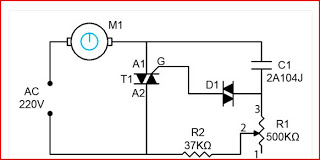
This is a simple ceiling fan regulator circuit diagram. It is used to control the speed of a ceiling fan. In other words, it is an AC motor speed controller circuit, as it controls the speed of an AC...
The BC547 transistor has a maximum operating current of 100 mA and a maximum voltage rating of 65 volts. When oriented with the label facing the viewer, the three terminals from left to right are collector, base, and emitter....
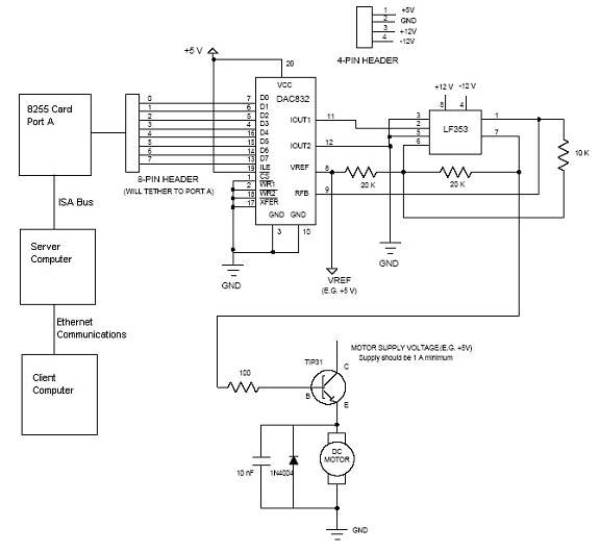
Open loop speed control of a DC motor is implemented using the 8255 Digital I/O Controller chip in conjunction with a TCP/IP server-client application programmed in Visual Basic. The DAC0832 chip serves as the Digital to Analog Converter. This...
This circuit is a Digital Radar Speedometer. It allows the evaluation of the speed of any moving object, particularly cars and other vehicles. The speed is measured in kilometers per hour (KPH) and is displayed using a three-digit format....
As high-performance microprocessors require increased power in automotive multimedia and telematics, commonly referred to as infotainment products, several well-known issues arise, including noise susceptibility, electromagnetic interference (EMI), and loop compensation, among others. Average current-mode control (ACMC) assists in mitigating...
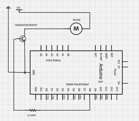
Is there a circuit that can be used to make a DC motor move randomly backward and forward, stop for a period, and then start again? Any assistance and ideas would be greatly appreciated. Research how to wire up...