
basic lift circuit four floors

The lift circuit operates using a series of interconnected components designed to facilitate vertical movement between floors in a building. The primary control element is the P1 push button, which initiates the lift's movement. Upon activation, a relay or motor driver circuit is engaged, powering the lift mechanism to ascend from the 1st floor to the 2nd floor.
The circuit may include a timer, which is crucial in determining the duration the lift remains at each floor. This timer can be implemented using a microcontroller or a simple RC timing circuit, depending on the complexity required. Once the timer elapses, a signal is sent to the lift control system, prompting it to engage the next relay or motor driver to continue the lift's journey to the 3rd floor.
Upon reaching the 3rd floor, the same process is repeated. The lift remains at this floor for a predetermined time before automatically moving to the 4th floor. This cycle of operation ensures that the lift is user-friendly and efficient, minimizing wait times for passengers.
Additional safety features may include limit switches that prevent the lift from exceeding its designated floors and emergency stop buttons that can be activated in case of malfunction. Power supply considerations must also be addressed, ensuring that the circuit can handle the load requirements of the lift motor while maintaining safety standards.
Overall, this basic lift circuit exemplifies a straightforward yet effective design for vertical transportation within a multi-story building.This is basic lift circuit. when press P1 push button lift starts to work 1st floor to 2 nd floor. Then after time duration it is automatically reach to 3 rd floor. And samething happen in 3rd floor & 4 th floor. 🔗 External reference
Related Circuits
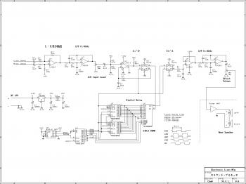
This is an easy-to-build surround sound processor circuit utilizing the digital delay processing method. This audio processor does not employ any specialized function integrated circuits that are difficult to obtain, and it is designed using only common-purpose integrated circuits....
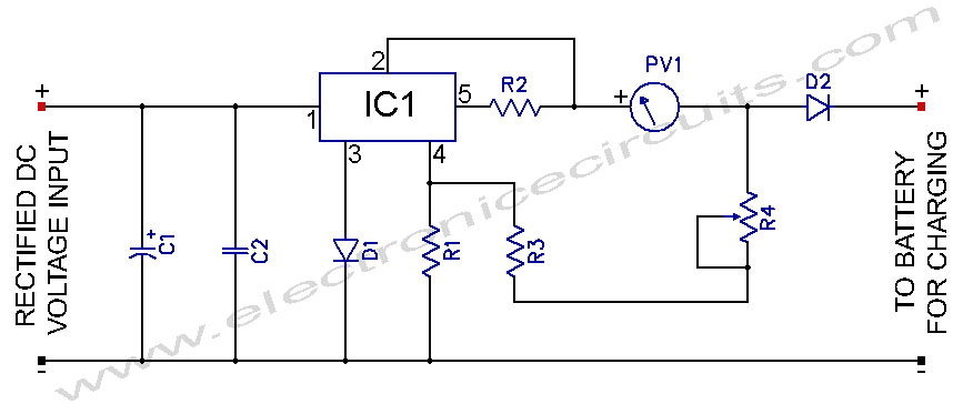
L200 12V Constant Voltage Battery Charger Circuit. This battery charger is based on the L200 regulator IC. The L200 is a five-pin adjustable voltage regulator. The L200 constant voltage battery charger circuit is designed to provide a stable 12V output...

This stereo amplifier utilizes the NE5517/A and features an excellent tracking accuracy of 0.3 dB, which is typical. The offset can be adjusted using the potentiometer, Rp. For AC-coupled amplifiers, the potentiometer can be substituted with two 5.1 k...
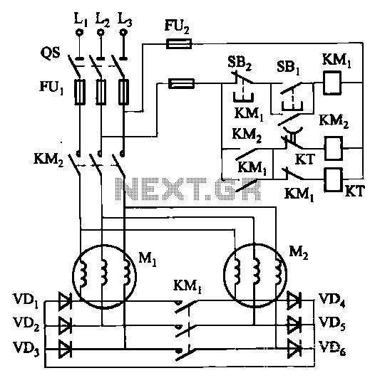
The circuit depicted in Figure 3-157 is designed for motors with a capacity of no more than 11 kW, requiring precise stopping capabilities. Upon shutdown, contact KMi releases, and the motor stator windings are configured into a three-phase rectifier...
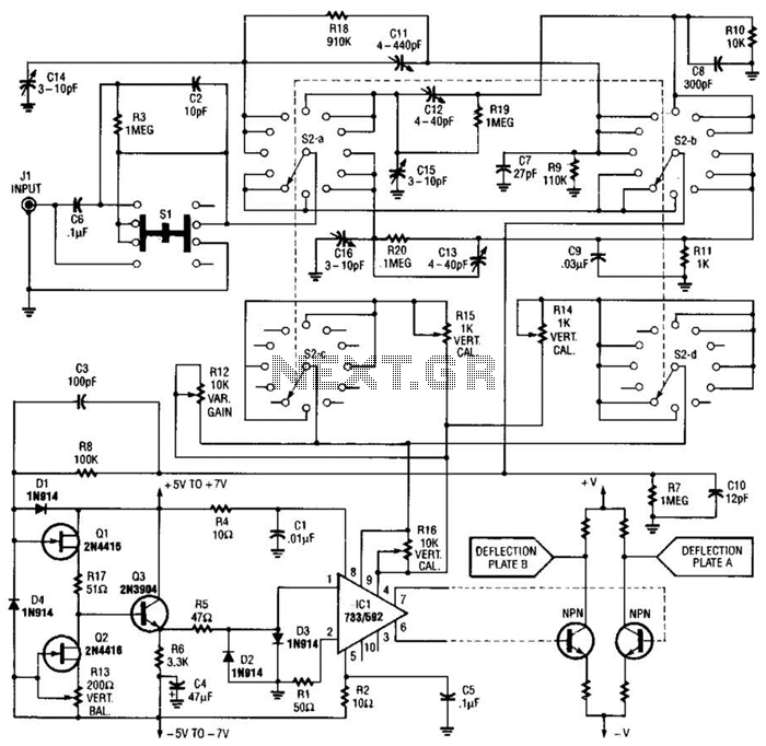
An oscilloscope front-end amplifier can be constructed using low-cost transistors and video amplifier integrated circuits (ICs). This preamplifier utilizes a FET input along with compensated attenuators, achieving an approximate bandwidth of 100 MHz, which is sufficient for most general-purpose...
This document presents plans for a simple ground plane antenna that is effective in the FM band (88-108 MHz). It is constructed from a small plastic disk. The 6 x 6 loop antenna, designed by Graham Maynard, is highlighted...