
Hf Low-Power Cw Transmitter

This 1.5-W transmitter circuit is designed for amateur radio operators, offering a compact and efficient solution for low-power transmission. The circuit operates from a 12-V power supply, making it suitable for various applications. The oscillator stage, represented by transistor Q1, utilizes an FT243 crystal for frequency stability, ensuring reliable performance within amateur bands.
Transistor Q2 functions as a buffer driver, providing impedance matching between the oscillator and the subsequent stages of the circuit. The keying mechanism is implemented through transistor Q5, which allows for on/off control of the transmitter, enabling operators to transmit signals as needed without affecting the oscillator's performance.
Transistor Q3 is employed as a driver for the final output stage, Q4, which is responsible for amplifying the signal to the desired output power level. It is crucial to attach a heatsink to Q4 to dissipate heat generated during operation, thus preventing thermal damage and maintaining efficiency. The output power from Q4 is approximately 1.5 W, suitable for short-range communication.
Coil specifications are essential for tuning the transmitter to the desired frequency, and these details are available in the parts list accompanying the schematic. Capacitor C12 plays a critical role in fine-tuning the circuit for optimal power output, and it should be adjusted to achieve the best performance in terms of signal clarity and transmission range.
Overall, this transmitter circuit offers a practical solution for amateur radio enthusiasts looking to build a low-power transmitter with straightforward components and clear operational characteristics. Suitable for amateur use, this 1.5-W transmitter runs on a 12-V supply. Ql is an oscillator using a surplus FT2 43 crystal. Q2 is a buffer driver and is keyed via keying transistor Q5. Q3 acts as a driver for Q4 (which should be heatsinked). Q4 develops about 1.5-W output. Coil data is given in the parts list. C12 is adjusted for best power output.
Related Circuits
This is an IR transmitting circuit which can be used in many projects. This IR transmitter sends 40 kHz carrier under computer control. The circuit can be controlled using any TTL or RS-232C level control signal which makes the...
The LM134 is an effective temperature sensor due to its highly linear output characteristic. As a current output device, it remains unaffected by certain environmental factors. The LM134 is a three-terminal device that operates as a current source, providing a...

This stereo FM modulator circuit utilizes the BH1417F FM stereo transmitter IC, which includes a stereo modulator for generating stereo composite signals and an FM transmitter for broadcasting an FM signal wirelessly. The stereo modulator produces a composite signal...
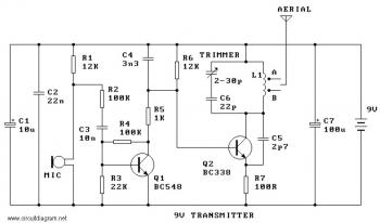
This is a simple and low-cost FM transmitter circuit. The frequency range of this FM transmitter is approximately 89 MHz to 109 MHz, with an output power of about 9 mW at 9 V. The circuit includes the following...
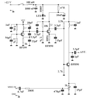
This video transmitter circuit operates on the UHF channel frequency of 470-580 MHz, specifically channels 21-34. It can transmit video signals over distances ranging from 30 to 100 meters when using a cable length of 10 to 20 cm....
This transmitters' intended purpose is for morse-code only in the 30 meter band (10Mhz). It is a low-power QRP type and needs to be connected to your existing tranceiver. The harmonic rejections on the prototype were measured at 40dB...