
bass and treble control without any ic and transistor

This bass treble circuit is designed to enhance audio signals by allowing users to adjust the bass and treble frequencies to their preference. The primary components include resistors and capacitors that form a passive equalizer network. The two potentiometers, designated for bass and treble control, allow for fine-tuning of the audio output. The bass control typically utilizes a low-pass filter configuration, which enables the user to boost lower frequencies, enhancing the depth and richness of the sound. Conversely, the treble control often employs a high-pass filter, which accentuates higher frequencies, contributing to clarity and brightness in the audio output.
The simplicity of the circuit is one of its key features, as it does not require complex components or extensive soldering techniques. This makes it an ideal project for beginners who are learning about audio electronics. The absence of a veroboard or PCB allows for a more hands-on approach, where hobbyists can directly engage with the components.
However, the circuit's reliance on passive components means that it may not deliver the same output power as more sophisticated active circuits that utilize operational amplifiers or dedicated power supplies. As a result, users may experience a lower volume level, which could be a limitation in certain applications. Furthermore, the non-linear behavior of the treble control may lead to an uneven response, where subtle adjustments in the potentiometer can result in significant changes in treble output, particularly at the extremes of the control range.
In summary, while this bass treble circuit offers an accessible introduction to audio electronics with its straightforward design and assembly, users should be aware of its limitations regarding output power and control linearity.This low cost bass treble circuit consists of some capacitors, resistors, and two T/C pot for BASS and TREBLE control. this circuit can be made without even a veroboard. You just solder components as this circuit network is not so complex. It has only two-pin parts. Let`s take a look at he circuit diagram. Nothing to say about it, as it is so simp le that a beginner level hobbyist can even understand and build this circuit. But there are some -ve points of this circuit which I must say, after giving you the circuit. As no external power supply, the O/P power is much lesser than I/P power, so volume decreases. The treble control doesn`t act as linear, it increases treble a lot in the end pot side 🔗 External reference
Related Circuits
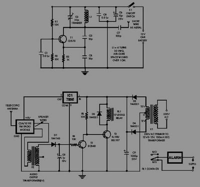
This circuit of an FM radio-controlled anti-theft alarm can be utilized with any vehicle that has a 6 to 12-volt DC supply system. The mini VHF FM transmitter is installed in the vehicle during the night when it is...
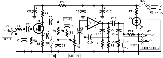
Tiny, portable guitar amplifiers are beneficial for practice while on the go and in bedroom or living room environments. Typically, they can be powered by batteries and include a headphone output. This project incorporates an FET input circuit with...
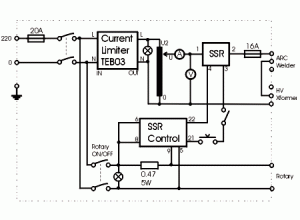
This shows the overall circuit diagram of the power control unit. On the left, there is a main relay controlled by the key switch. The power control unit circuit diagram illustrates the fundamental components and their interconnections, providing a clear...
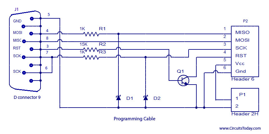
ISP programmer with circuit diagram for AVR Atmega32 microcontroller. This ISP burner circuit is an adaptation of the Pony programmer and uses PonyProg software. The ISP (In-System Programming) programmer designed for the AVR Atmega32 microcontroller allows for programming the microcontroller...
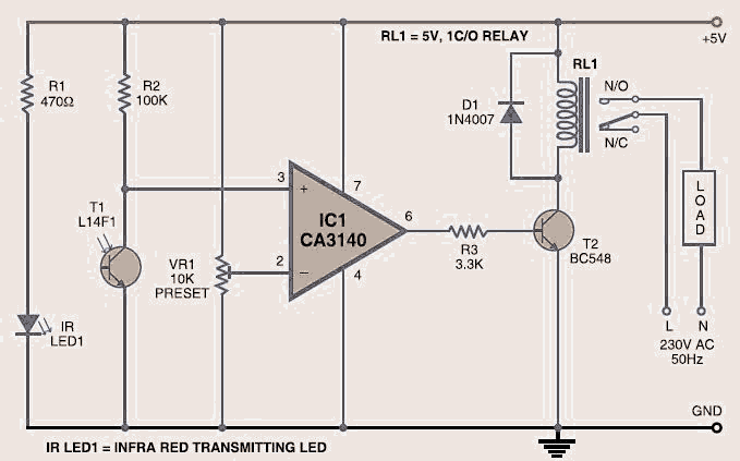
The wireless light switch circuit described here requires no physical contact for operating the appliance. You just need to move your hand between the infrared LED (IR LED1) and the phototransistor (T1). The infrared rays transmitted by IR LED1...

Sip-and-Puff (SNP) controllers are widely recognized devices, often utilized in electric wheelchairs, enabling individuals with limited hand mobility to control their wheelchairs or other devices through inhaling (sipping) or exhaling (puffing) into a straw. The intensity of the inhalation...