
fm radio controller anti theft alarm

The FM radio-controlled anti-theft alarm circuit is designed for effective vehicle security by utilizing a compact transmitter-receiver setup. The transmitter, which operates within the VHF FM band, is strategically installed in the vehicle, ensuring that it remains concealed and functional during nighttime parking. The receiver, based on the CXA1019 IC, is tuned to the specific frequency emitted by the transmitter, creating a reliable communication link.
In normal operation, when the vehicle is stationary and the transmitter is powered, the receiver outputs a clean signal with no interference, allowing transistor T2 to remain in the off state. This configuration ensures that the relay driver transistor T3 does not activate, keeping the relay de-energized and the alarm system inactive.
The critical element of this system is its response to unauthorized movement. If an intruder attempts to drive the vehicle away, the distance between the transmitter and receiver increases, breaking the radio link. This disruption triggers the FM radio module to output a hissing noise, which is an indication of alarm activation. The generated hissing AC signals are coupled to the relay switching circuit through an audio transformer, effectively energizing the relay and triggering the alarm mechanism.
The relay, once energized, can be connected to various alarm systems, such as sirens or flashing lights, enhancing the overall security of the vehicle. The use of a 10k resistor (R5) ensures appropriate base biasing for transistor T3, allowing for reliable operation of the relay driver circuit.
Overall, this FM radio-controlled anti-theft alarm circuit offers a cost-effective and efficient solution for vehicle security, leveraging simple components to provide a robust defense against theft.This Circuit of FM radio-controlled anti- theft alarm can be used with any vehicle having 6- to 12-volt DC supply system. The mini VHF, FM transmitter is fitted in the vehicle at night when it is parked in the car porch or car park.
The receiver unit with CXA1019, a single IC-based FM radio module, which is freely available in the market at reason able rate, is kept inside. Receiver is tuned to the transmitter`s frequency. When the transmitter is on and the signals are being received by FM radio receiver, no hissing noise is available at the output of receiver. Thus transistor T2 (BC548) does not conduct. This results in the relay driver transistor T3 getting its forward base bias via 10k resistor R5 and the relay gets energised.
When an intruder tries to drive the car and takes it a few metres away from the car porch, the radio link between the car (transmitter) and alarm (receiver) is broken. As a result FM radio module gene-rates hissing noise. Hissing AC signals are coupled to relay switching circ- uit via audio transformer. 🔗 External reference
Related Circuits
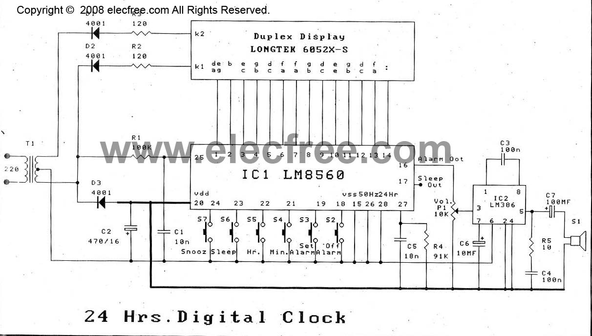
The digital time clock circuit is of great interest to electronic amateurs. The most popular clock ICs include the LM8361 and MM5387. Unfortunately, these ICs... The digital time clock circuit serves as an essential component for various electronic applications, providing...
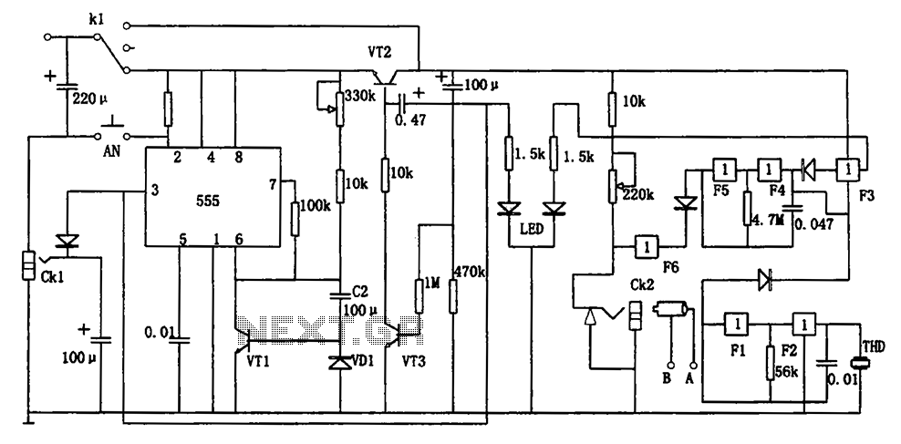
The circuit represents a general multi-function alarm and timing mechanism. Its timing capabilities range from 5 minutes to 3 hours. The timing components include C2, VD1, and VT1. The circuit utilizes a capacitance multiplier with a 555 timer. CK1,...
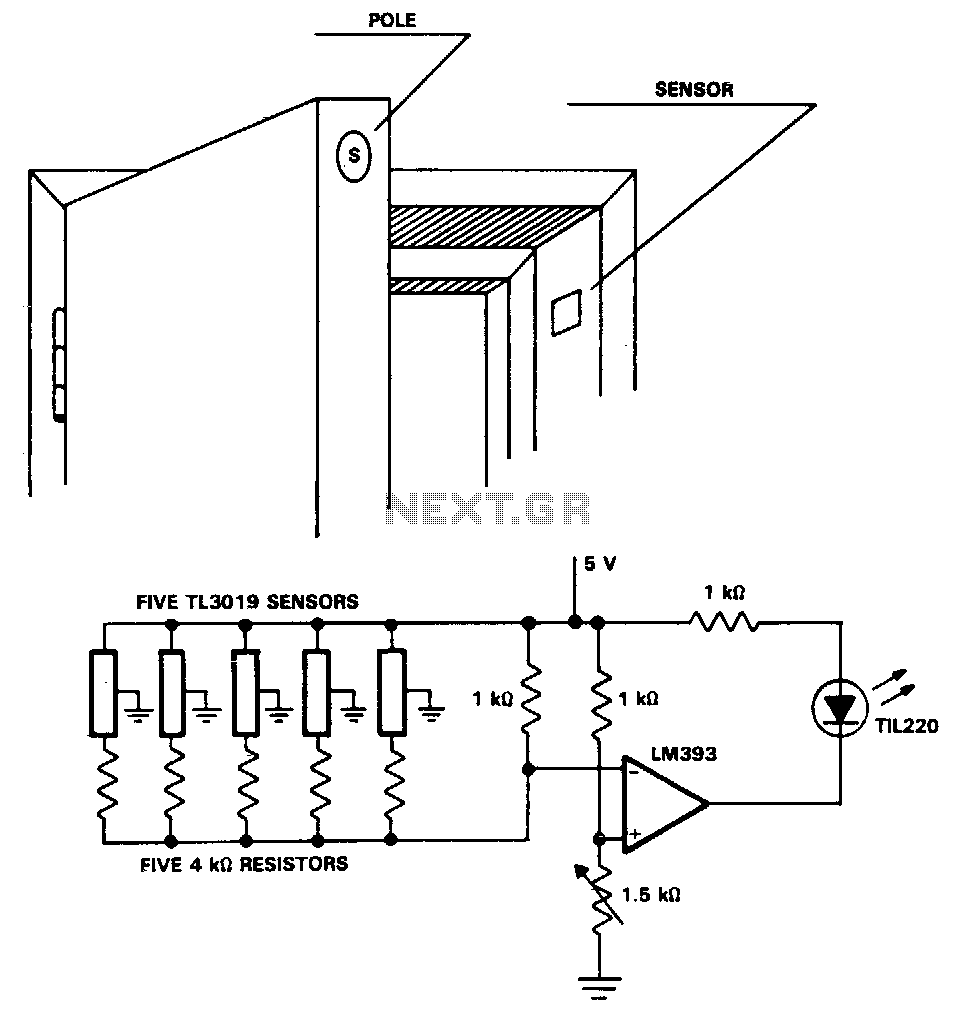
The TL3019 device activates, or goes low, when a south pole of a magnet approaches the chip face. In this example, there are five doors, each equipped with a magnet embedded in its edge, with the south pole facing...
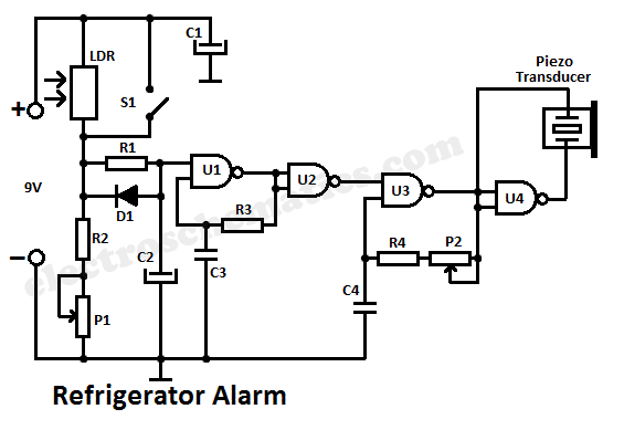
A simple light fence security beeper is presented. This circuit can function as a door alarm, gate alarm, pathway alarm, etc. It can be powered by any 12 Volt DC power supply. The operation of this circuit is straightforward....
This circuit cannot be shut off for 10 to 60 seconds, even if the trip condition is immediately removed. It draws no standby power from the battery and is self-resetting. The described circuit operates under a delay mechanism that...
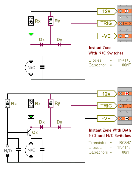
The Transistor Burglar Alarm System allows for the addition of multiple extra zones. The primary circuit is compatible with standard normally-closed input devices, including magnetic reed contacts, micro switches, foil tape, and passive infrared sensors (PIRs). An auxiliary circuit...