
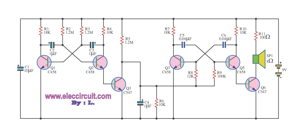
bass booster circuit

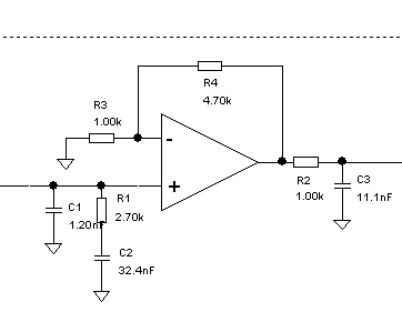
The bass booster circuit operates by selectively amplifying the lower frequency range, typically between 20 Hz to 200 Hz, which corresponds to the bass frequencies in audio signals. This enhancement is achieved through the use of operational amplifiers (op-amps) and passive components such as resistors and capacitors.
The core of the bass booster circuit involves a low-pass filter configuration that allows the desired bass frequencies to pass while attenuating higher frequencies. The cutoff frequency is determined by the values of the resistors and capacitors in the filter. Typically, a gain stage is added to amplify the filtered signal, ensuring that the output level is sufficient for driving speakers or headphones.
In addition to the basic low-pass filter design, the circuit may include features such as adjustable gain, which can be implemented using a variable resistor (potentiometer). This allows users to control the level of bass enhancement according to their preferences.
The output stage of the circuit is crucial, as it must be capable of driving the load without distortion. Depending on the application, the output can be connected directly to a speaker or to a power amplifier. Proper power supply decoupling is also essential to prevent noise from affecting the performance of the bass booster.
Overall, this bass booster circuit design provides a straightforward and effective means of enhancing low-frequency audio signals, making it suitable for various audio applications, including home audio systems, car audio, and portable speakers.Bass booster of this website is used to boosts the beat frequency without effect the high frequency circuit diagram of bass booster bass booster and different radio circuit. 🔗 External reference
Related Circuits
Described timer to participate in the current circuit switch - bulb without any modification of existing pipelines. Connect the timer is in Figure 1 The time switch has only two outlets, which is connected in parallel to the button...
This circuit generates a sound similar to that of ambulance sirens. It differs from typical ambulance siren circuits in its design. The circuit utilizes a combination of oscillators and amplifiers to produce a sound that mimics the varying pitch and...

This circuit generates a siren sound when switch S1 is pressed. The sound frequency increases as capacitor C1 charges, and when switch S1 is released, the frequency decreases as capacitor C1 discharges. The circuit operates on a simple principle of...
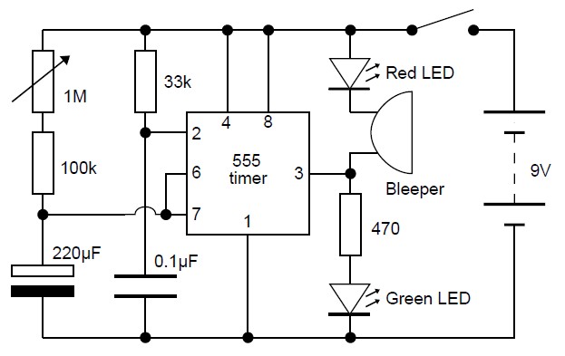
This adjustable analog timer circuit begins timing when it is activated. A green LED illuminates to indicate that the timing is in progress. Upon completion of the set time period, the green LED turns off, a red LED activates,...
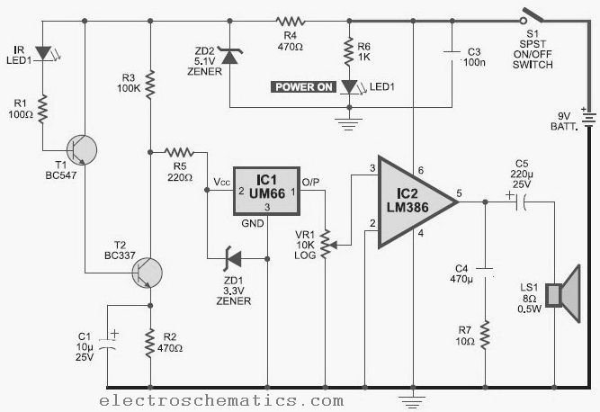
This infrared detector is capable of detecting the presence of modulated infrared signals in its vicinity from various electronic sources, such as an IR handheld remote. The infrared detector operates by utilizing a photodetector that is sensitive to infrared light....
A problem has been encountered in a Phase-Locked Loop (PLL). A loop filter has been utilized, but the output spectrum does not meet expectations. In a Phase-Locked Loop (PLL) system, the loop filter plays a crucial role in determining the...