
Spur Problem in a PLL Circuit

In a Phase-Locked Loop (PLL) system, the loop filter plays a crucial role in determining the performance characteristics of the PLL, including its stability and the quality of the output signal. The loop filter typically consists of passive and/or active components that shape the feedback signal from the output to the phase comparator, thereby influencing the dynamic response of the PLL.
When designing a loop filter, it is essential to consider the desired bandwidth and phase margin to ensure that the PLL can effectively lock onto the reference frequency. Common configurations for loop filters include first-order, second-order, and higher-order filters, each offering varying levels of complexity and performance. The choice of filter topology directly impacts the output spectrum, which may exhibit issues such as excessive noise, unwanted harmonics, or insufficient locking range if not properly designed.
In this case, the output spectrum indicates that there may be design flaws in the loop filter or an incorrect configuration of the PLL components. Possible causes for the observed output spectrum could include improper component values, incorrect filter topology, or external interference affecting the PLL operation. To address the issue, a thorough analysis of the loop filter design, including simulations and adjustments to component values, is recommended. Additionally, evaluating the phase comparator and VCO (Voltage-Controlled Oscillator) characteristics can provide further insights into the PLL performance and help identify potential improvements.Hello friends I have a problem in a PLL. I have used a loop filter as shown in this figure: But the output spectrum is as shown in this figure: What`s .. 🔗 External reference
Related Circuits
This document presents plans for a simple ground plane antenna that is effective in the FM band (88-108 MHz). It is constructed from a small plastic disk. The 6 x 6 loop antenna, designed by Graham Maynard, is highlighted...
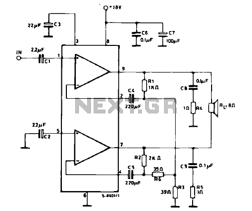
The schematic illustrates a 12 W Bridge Amplifier circuit diagram utilizing the TDA2007A, a class AB dual audio power amplifier. This amplifier is specifically designed for stereo applications in music centers, television receivers, and portable radios. As stated in...
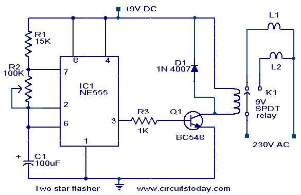
A circuit designed to alternately flash two Christmas stars is presented. The NE555 integrated circuit (IC1) is configured as an astable multivibrator. When IC1 outputs a positive pulse, transistor Q1 becomes conductive, activating relay K1. Consequently, lamp L2, connected...
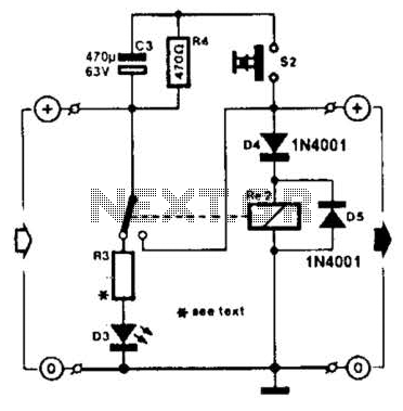
A charged capacitor C3 and a momentary pushbutton switch S2 are utilized to temporarily activate relay RE2. The battery being charged powers the relay to maintain its closed state. Additionally, S2 can energize the relay even if the battery...
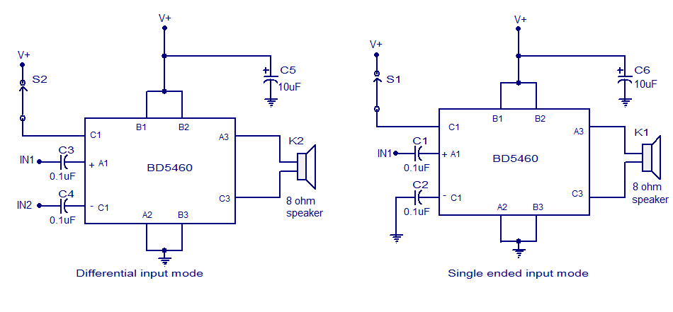
The BD5460 is a low power Class D amplifier that can be utilized in low power applications such as handheld audio devices. The BD5460 does not require an LC filter at the speaker output and can be powered by...
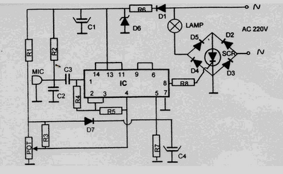
This 220 Volt disco lamp circuit is not a voice switch (VOX), as it cannot differentiate between musical sounds and human voices. Instead, it functions as a sound-activated device. An interesting application of this circuit is to control the...