
Remote Controlled Fan Regulator
This project involves designing a remote-controlled AC fan regulator that allows users to adjust the fan speed in ten distinct stages. The core of the circuit is based on the ATmega8 microcontroller, which provides the necessary processing power to interpret remote control signals and adjust the fan speed accordingly.
The circuit design includes an infrared (IR) receiver that captures signals from a remote control. The ATmega8 processes these signals to determine the desired fan speed. The microcontroller is programmed to control a triac or a solid-state relay, which in turn regulates the AC power supplied to the fan motor. This method of control allows for smooth speed adjustments, minimizing noise and flicker that can occur with less sophisticated methods.
The PCB layout is designed to accommodate all components, including the microcontroller, IR receiver, power supply circuitry, and the triac or relay interface. Careful attention is given to the placement of components to optimize performance and minimize electromagnetic interference. The source code provided is written in C, utilizing the AVR-GCC compiler, and includes functions for initializing the microcontroller, reading input from the IR receiver, and controlling the output to the fan.
Overall, this project combines both hardware and software elements to create an effective and user-friendly solution for controlling AC fan speeds remotely. The comprehensive documentation ensures that users can replicate the design and understand the functionality of each component within the circuit.A detailed DIY remote controlled AC Fan regulator with 10 stage speed control. Made with ATmega8, full source code and PCB Layout.. 🔗 External reference
Related Circuits
The old and omnipresent NE555 can be very good at something it was not meant for: driving relays or other loads up to 200 mA. The picture shows an example circuit: if the input level rises over 2/3 of...
The DTMF infrared remote control circuit utilizes a DTMF encoded signal that can be decoded by a specialized decoder and the PLL audio decoder LM567. However, a DTMF encoded signal decoded by a single decoder yields only one frequency....
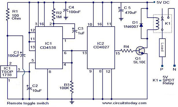
At the application level, this circuit is similar to the previously mentioned circuit, with the primary distinction being the method of implementation. This circuit is designed to toggle any electrical appliance between ON and OFF states using a TV...
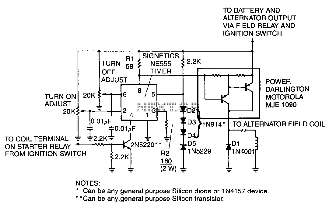
A monolithic 555-type timer serves as the core component of this straightforward automobile voltage regulator. When the timer is inactive, resulting in a low output at pin 3, the power Darlington transistor pair remains off. If the battery voltage...
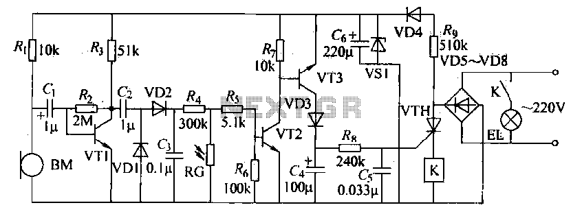
The voice circuits discussed in this section operate such that during daylight or in bright conditions, the voice-activated switch remains off, preventing the lamp from lighting. Conversely, in low-light conditions or at night, the sound control switch is activated....
A 567 IC tone decoder/detector can be utilized to construct a remote control or intercom system. This circuit is capable of controlling a relay or transmitting an audio signal. The 567 IC is a versatile integrated circuit designed for tone...
Warning: include(partials/cookie-banner.php): Failed to open stream: Permission denied in /var/www/html/nextgr/view-circuit.php on line 713
Warning: include(): Failed opening 'partials/cookie-banner.php' for inclusion (include_path='.:/usr/share/php') in /var/www/html/nextgr/view-circuit.php on line 713