
DC motor speed control

The circuit operates by leveraging the characteristics of the 4011 CMOS NAND gate, which is configured to generate a square wave signal. This signal, when passed through the diodes, allows for the modulation of the voltage applied to the motor. The diodes ensure that the current flows in one direction, preventing back EMF from the motor from affecting the circuit's operation. The NPN power transistor acts as a switch, controlled by the output of the NAND gate, allowing for the rapid on-off cycling that defines pulse width modulation (PWM).
The speed control mechanism can be implemented using a variable resistor or a potentiometer, which adjusts the duty cycle of the PWM signal. As the duty cycle increases, the average voltage supplied to the motor also increases, resulting in higher speeds. Conversely, reducing the duty cycle lowers the average voltage, allowing for finer control at lower speeds. This method is particularly advantageous for applications requiring precise speed adjustments, such as in robotics or conveyor systems.
At low speeds, the motor receives short bursts of power, which keeps it moving without overheating. The design ensures that the motor is not subjected to continuous high voltage, which could lead to thermal issues. As the speed increases, the motor's operation becomes more stable, resembling its behavior in a direct connection to a DC source. This circuit is beneficial for applications where energy efficiency and precise control over motor speed are critical, as it minimizes wasted power while maximizing operational effectiveness.The circuit uses a 4011 CMOS NAND gate, a pair of diodes and an NPN power transistor to provide a variable duty-cycle dc source. Adjusting the speed control varies the average voltage applied to the motor. The peak voltage, however, is not changed. This pulse power is effective at very low speeds, constantly kicking the motor along At higher speeds, the motor behaves in a nearly normal manner.
Related Circuits
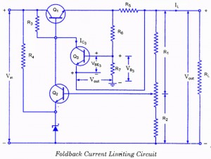
If the load resistance (RL) is reduced or the load terminals are accidentally shorted, a very large load current will flow, potentially damaging the pass transistor (Q1), diode, or other components. Fuse protection may not be sufficient, as the...
When the fan seized up in my source and I changed it to a type with much less noise, turned on my computer, the largest source of noise CPU cooler fan. The computer I have a boxed Pentium III...
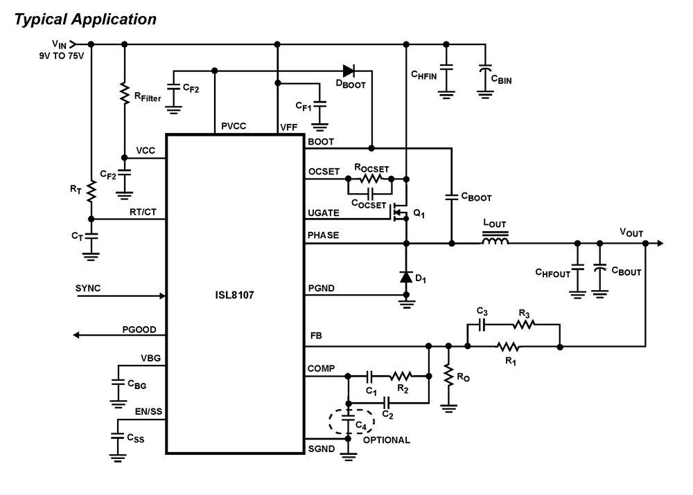
The ISL8107 is a single-phase, non-synchronous buck controller equipped with an integrated high-side MOSFET driver. It operates within an input voltage range of 9V to 75V. The internal reference voltage is 1.192V with a tolerance of ±1% across the...
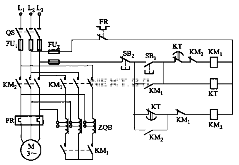
The circuit depicted in Figure 3-49 illustrates an autotransformer that is controlled by a time relay (KT). The delay time set by the KT relay corresponds to the motor's startup duration. The circuit utilizes an autotransformer, which is a type...
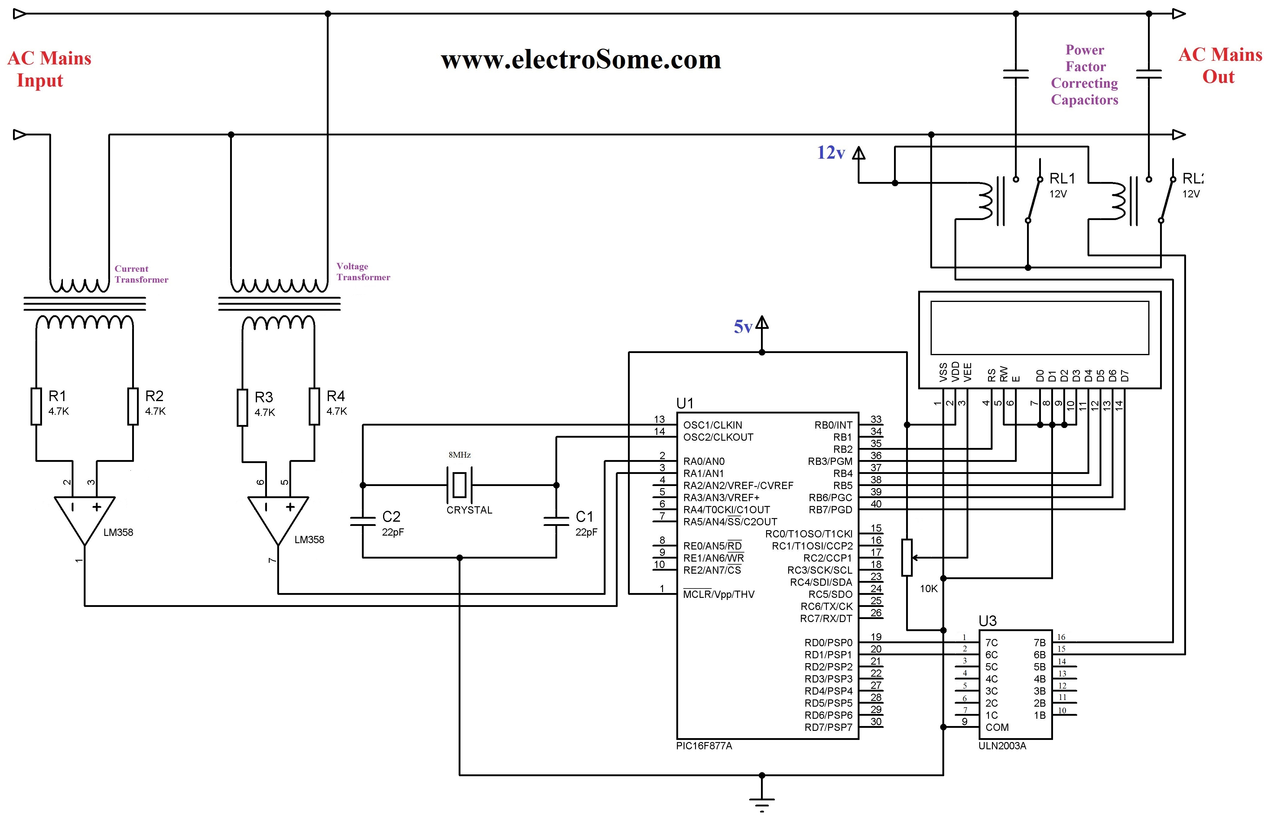
The 230 V, 50 Hz supply is stepped down using a voltage transformer, while a current transformer is utilized to extract the current waveforms. The output of the voltage transformer corresponds to the voltage across the load, and the...
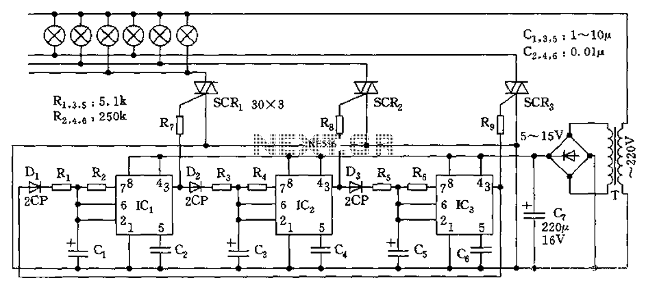
The circuit utilizes a 555 timer as its core component to control three lights through a cyclic trigger monostable delay circuit. The brightest light is controlled by a silicon-controlled rectifier (SCR) that determines the cycle of illumination. When pin...