
Bathroom automatic hand dryer circuit

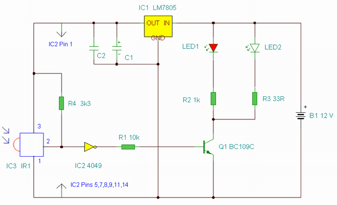
The bathroom automatic hand dryer circuit utilizes an infrared opto coupler consisting of an LED and a photosensitive transistor (VT) to detect the presence of hands. This detection is crucial for the automatic operation of the hand dryer. The circuit is designed to minimize energy consumption by activating the heating element only when necessary.
The control element of the circuit is the 1WH8778 switch integrated circuit. This IC is responsible for processing the signals received from the infrared opto coupler. When the LED emits infrared light, it is reflected off the hands and detected by the photosensitive transistor. The presence of hands causes the voltage at the input of the TWH8778 to rise to approximately 1.6V. This voltage level is sufficient to turn on the switch integrated circuit, allowing current to flow through a resistor (R).
The flow of current through the resistor triggers the crystal field management (VTH), which activates the far infrared heating element (EH). This heating element is designed to quickly dry hands using infrared radiation, providing a hygienic and efficient drying method.
Once the hands are removed from the detection area, the infrared light is no longer reflected to the photosensitive transistor. This change in signal leads to the automatic cut-off feature being activated, which deactivates the switch integrated circuit and stops the operation of the heating element. This feature not only conserves energy but also enhances the safety of the device by preventing overheating.
Overall, the circuit design emphasizes efficiency and user convenience, making it an effective solution for automatic hand drying in bathroom settings. Bathroom automatic hand dryer circuit. Figure, LED to LED tube takes; VT is a photosensitive transistor, LED and VT composition infrared opto tuner, as a signal sensing clamor, 1WH8778 switch integrated circuit as the control element. When the optical coupler hands in the following, feet high potential TWH8778 switch integrated circuit is turned almost 1.6V, current through R, double trigger to make it crystal f field management VTH conduction, far infrared heating line identified EH is working hand drying. After leaving the hand, automatic cut-off switch circuit, EH to stop working.
Related Circuits
This is an enhanced infrared (IR) remote control extender circuit. It features high noise immunity, resistance to ambient and reflected light, and an increased operational range. The improved IR remote control extender circuit is designed to extend the range of...
This circuit is designed for an electrically operated rolling shutter, typically featuring a standard control panel with a three-position switch: up, down, and stop. To automate the opening and closing with a time-controlled switch, additional wiring connections are required....
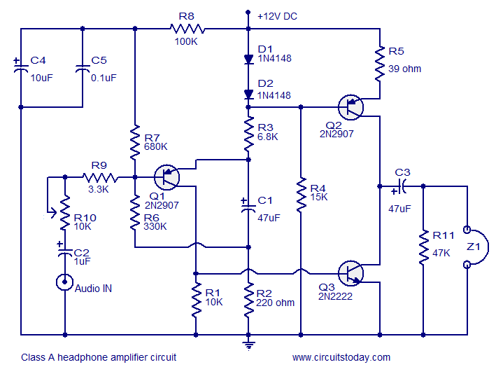
Transistor amplifier circuits that are simple and easy to construct. This includes a headphone amplifier, a four-transistor amplifier, and a low-power amplifier. Transistor amplifier circuits are fundamental components in electronic design, offering various applications ranging from audio amplification to signal...
There are two independent modeling light circuits for the P2000D, one for each of the two channels. The modeling light circuit is completely separate from the high voltage strobe circuitry, even featuring its own On/Off switch. Therefore, the functionality...

The schematic for this project is designed to be very simple, utilizing a minimal number of components to keep costs and assembly time low. The primary components in the schematic include the PIC 18F452 microcontroller, a tilt sensor, and...
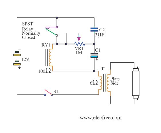
This is a flashing blink circuit designed for 12V applications. It utilizes a small-sized fluorescent lamp and operates through a relay that modifies the circuit from DC to AC. The flashing blink circuit operates at a voltage of 12V, making...