
rolling shutter motor control circuit

The electrically operated rolling shutter circuit is a practical solution for automated control, enhancing convenience and functionality. The three-position switch allows for manual operation, providing flexibility in controlling the shutter's position. For automation, the integration of a timer introduces a programmable element, enabling users to set specific times for the shutter to open or close, thus optimizing energy efficiency and security.
The relay plays a crucial role in this circuit, acting as an interface between the timer and the shutter motor. When the timer is activated, it energizes the relay coil, which in turn closes the relay contacts, allowing current to flow to the shutter motor. The choice of a 230-V relay ensures compatibility with standard mains voltage, while the relay's design must accommodate the current requirements of the shutter motor to prevent overheating or failure.
Safety considerations are paramount in this design. The changeover switch must be robust and rated for 230 VAC to prevent electrical hazards during operation. This switch not only allows users to toggle between automatic and manual modes but also serves as a safeguard against conflicting commands. By preventing simultaneous activation of both modes, the risk of mechanical failure or damage to the shutter system is significantly reduced.
The use of a plastic mains adapter enclosure is recommended for housing the relay and switch. This enclosure protects the components from environmental factors and accidental contact, ensuring safe operation. The built-in plug facilitates easy connection to the timer, streamlining the installation process.
In summary, the circuit design for the electrically operated rolling shutter incorporates essential components such as a three-position switch, a timer, a 230-V relay, and a safety-rated changeover switch. This configuration not only enhances automation but also prioritizes user safety and operational reliability. Proper installation and adherence to electrical standards will ensure the effective performance of the rolling shutter system.This is a circuit for an electrically operated rolling shutter usually has a standard control panel with a three-position switch: up, down and stop. If you would like to automate the opening and closing with a time controlled switch, a few additional wires will have to be connected.
Typically, the controls are implemented as indicated in the schem atic Normal Situation`. This is the figure of the circuit; If this is indeed the case, then you can see in New Situation` how the shutter can be automated with a timer. There is only one method to determine the actual schematic of your control circuit, and that is to open the control box and using an ohmmeter, pencil and paper to check out and draw the circuit.
Make sure you turn the power off ¬rst though! Connect a 230-V relay (with both the contacts and the coil rated 230 VAC) to the timer. The changeover switch between automatic and manual control needs to be rated 230 VAC as well and may not be a hazard for the user. The relay and switch are preferably fitted in a plastic mains adapter enclosure with built-in plug, which is plugged into the timer.
It is a good idea to check first if this will actually ¬t. Because of the manual/automatic-switch, the operation is completely fail-safe and misunderstandings are out of the question. The switch prevents the issue of conflicting commands (with disastrous consequences) when, for example, the shutter is being automatically raised and manually lowered at the same time.
🔗 External reference
Related Circuits
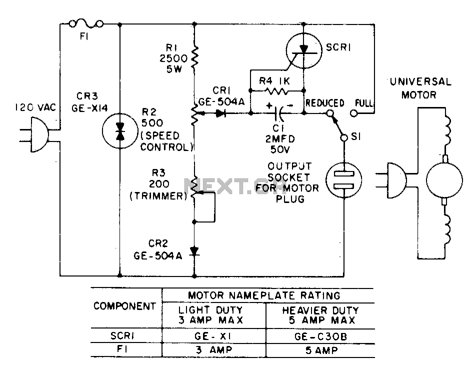
Most standard household appliances and portable hand tools can be adapted for variable-speed operation using a simple half-wave SCR phase control. This device can serve as the speed control unit for typical loads, provided they utilize series universal (brush...
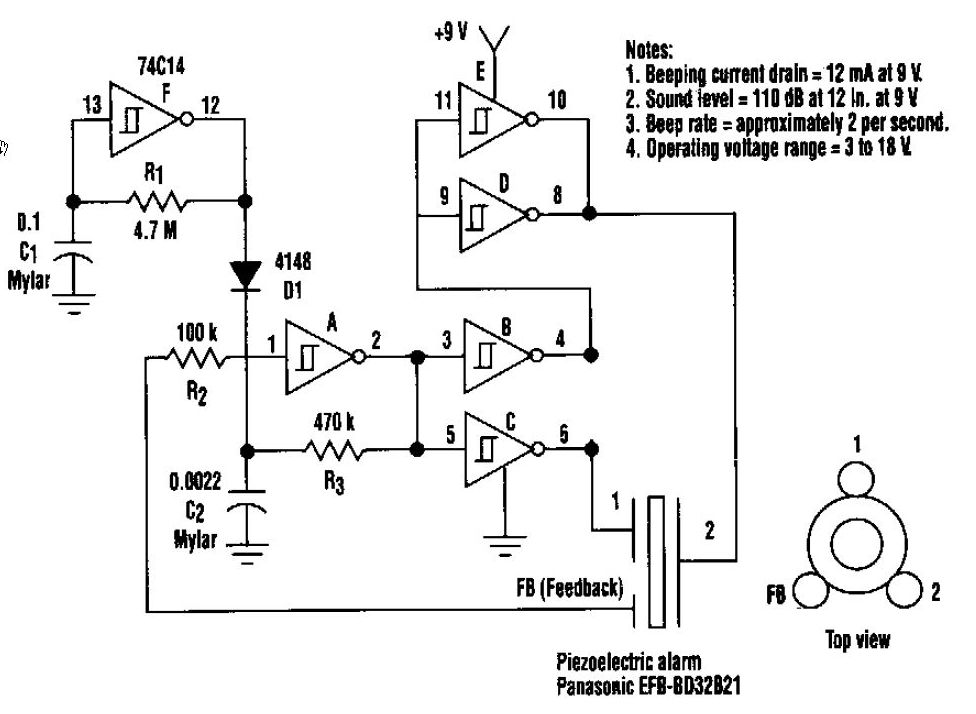
This beeper circuit generates an impressive 110dB sound level from a 9V supply. The design employs a single 74C14 (CD40106B) CMOS hex inverting Schmitt-trigger integrated circuit (IC), which must be paired with a piezoelectric device featuring a feedback terminal....
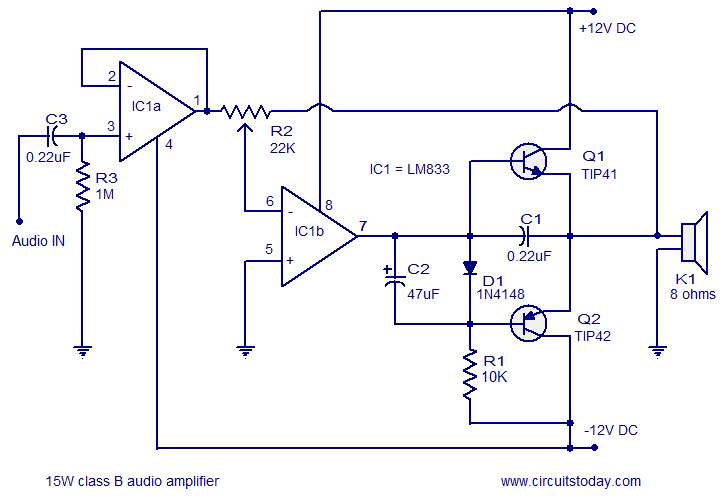
A 15 Watts Class B audio amplifier circuit is designed using a dual op-amp LM833. The schematic diagram is provided, and a potentiometer allows for volume control. The 15 Watts Class B audio amplifier circuit utilizes the LM833 dual operational...
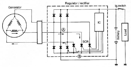
The circuit of the Suzuki GSX1300 Hayabusa charging system consists of a generator, a regulator/rectifier unit, and a battery. The alternating current (AC) generated by the generator is rectified by the rectifier to produce direct current (DC), which is...
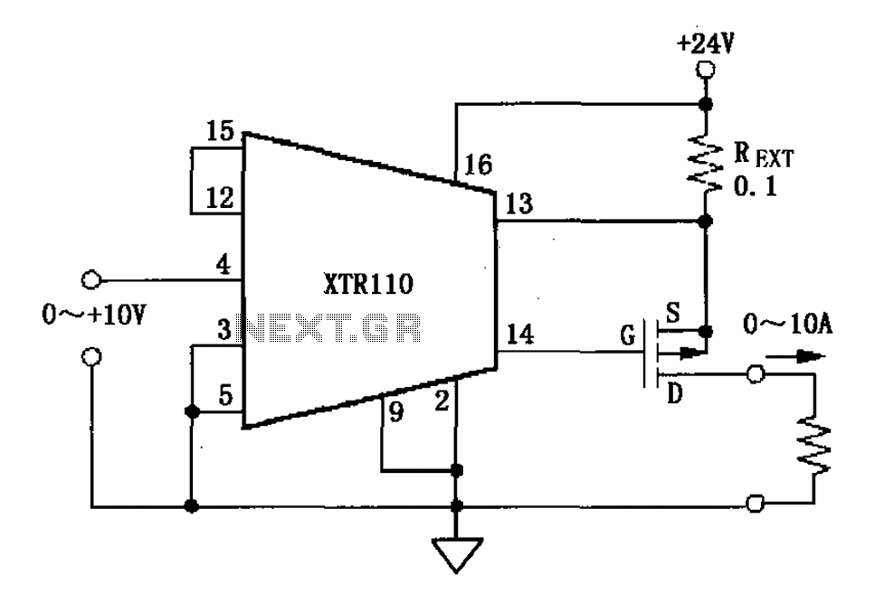
When the output current exceeds 40mA, the XTR110 requires the use of an external resistor (REXT) instead of the internal 50-ohm resistor (R9). REXT should be connected between pin 13 and pin 1. The value of REXT is determined...
A brief background is provided, indicating a basic understanding of electronics, including knowledge of component functions and schematic reading, but lacking further expertise. The circuit in question appears to involve fundamental electronic components, which may include resistors, capacitors, diodes, transistors,...