
batteries charger and psu circuit

The circuit design incorporates a battery charger section that is optimized for charging lithium-ion or nickel-metal hydride batteries. The charger utilizes a linear voltage regulator or a switching regulator to maintain a stable 5V output. This section typically includes components such as a transformer (if AC input is used), rectifiers to convert AC to DC, and filtering capacitors to smooth the output voltage. Protection features, such as overvoltage and overcurrent protection, may also be integrated to ensure safe operation during the charging process.
The regulated power supply section of the circuit employs an adjustable voltage regulator, which can be implemented using a variable resistor (potentiometer) in conjunction with a linear voltage regulator, such as the LM317. This allows the user to set the output voltage anywhere between 2V and 9V, depending on the requirements of the connected load. The circuit may include additional filtering capacitors to reduce noise and improve voltage stability, along with heat sinks to manage thermal dissipation from the voltage regulator.
Overall, this circuit provides a versatile solution for charging batteries and supplying variable voltage to various electronic devices, making it suitable for a wide range of applications in both hobbyist and professional settings.There are two parts in this circuit, ie the battery charger with a fixed output voltage, which is 5VDC. Another part is the regulated power supply that can be regulated output voltage between 2-9 volts. 🔗 External reference
Related Circuits
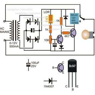
This circuit diagram illustrates a light-activated switch utilizing the National Semiconductor comparator IC LM311 and a light-dependent resistor (LDR). The configuration is based on a voltage comparator circuit centered around IC1. The non-inverting input of IC1 receives a reference...
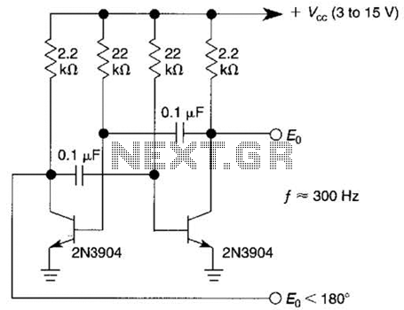
This free-running square-wave oscillator utilizes two NPN transistors. The output frequency is approximately 300 Hz with the specified component values. The circuit operates as a basic oscillator, generating a square wave output through the interaction of two NPN transistors. The...

This device offers numerous implementation possibilities due to its wide input voltage range and large maximum output current across a broad output voltage spectrum. It features long battery life and low power consumption owing to its high efficiency and...
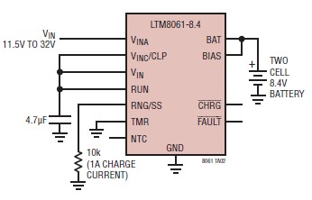
A simple and efficient lithium battery charger and monitoring system can be designed using the LTM8061 integrated circuit from Linear Technology. The LTM8061 is a high-efficiency 32V, 2A module standalone lithium battery charger optimized for one- and two-cell packs,...
This circuit is a low-frequency Wien bridge sinusoidal oscillator designed for the audio range, characterized by very low distortion, making it suitable for testing various audio equipment. The circuit has undergone thorough testing, and a printed circuit board (PCB)...
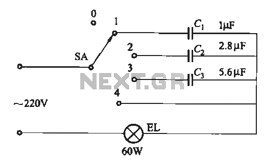
A dimming circuit capacitor circuit is illustrated in Figure 2-63. When the switch SA is moved from position "1" to "3," the capacitance increases in ascending order, resulting in the light bulb brightness also increasing correspondingly. When SA is...