
Dimming circuit using capacitance

A dimming circuit utilizing capacitors is commonly employed to control the brightness of incandescent lamps. The circuit operates by adjusting the capacitance in relation to the power supplied to the lamp. The switch SA serves as a variable control that allows the user to select different capacitance levels, thereby modulating the light output.
In position "1," the circuit connects to a minimal capacitance value, resulting in low brightness. As the switch is moved through the positions "2" and "3," the capacitance increases sequentially, allowing more current to flow to the lamp and thereby increasing the brightness. Position "0" effectively disconnects the circuit, turning the lamp off. Position "4" connects the circuit to its maximum capacitance, delivering the highest current and resulting in maximum brightness.
The formula provided for estimating capacitance, C = O i Lu kettle of 066 million pF, indicates that the capacitance value is directly influenced by the power rating of the lamp, denoted as P in watts. This relationship is crucial for ensuring that the circuit operates within safe limits, particularly when using components rated for higher voltages, such as those above 300V, which are necessary to handle the potential voltage spikes in the circuit. The CJ41 CBB22 type capacitor is recommended due to its reliability and performance characteristics in high-voltage applications.
This dimming circuit is an essential component in lighting control systems, providing flexibility and energy efficiency by allowing users to adjust the intensity of light according to their needs. Proper selection of capacitors and understanding of the circuit's operational principles are vital for optimal performance and safety.(1) dimming circuit capacitor circuit shown in Figure 2-63. When the switch SA from "1" hit "3" position, in ascending order of capacity, light bulb degree also in ascending order. When SA hit the "0" position, the lamp, and when SA hit the "4" position, the brightest. Capacitance can be estimated by the following formula: . C = O i Lu kettle of 066 million 'pF) ~ / formula P- lamp power rating. W ' P. - Dimming after power, w. Optional voltage above 300V or CJ41 CBB22 type capacitor.
Related Circuits
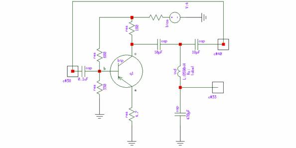
To demonstrate Rincon's capability to simulate autonomous circuits, a one-transistor oscillator utilizing a phase-inverting resonance T-shape LC circuit is considered. The schematic of this simulator is illustrated in Figure 1. The design of the simulator is detailed in reference...
Features: 1. The operating voltage is low, functioning with a single supply of 2.0V. 2. Power consumption is minimal, with a supply current of 5 µA at 32 kHz and 130 µA at 1 MHz. 3. It has a...
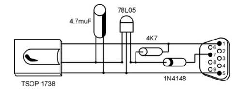
It is unusual that personal computers are not equipped with a standard remote control interface. Many motherboards feature an IRDA port; however, this port is not compatible with the 38 kHz frequencies commonly used by regular remote controls. Fortunately,...
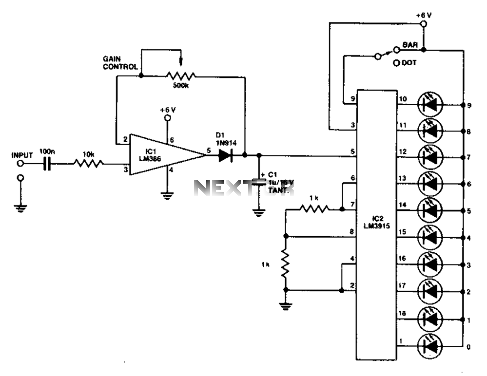
A simple level power meter designed to provide a high-fidelity sound system with a bar or dot matrix display. The green LED display indicates levels from 0 to 7; level 8 is shown in yellow, and level 9 is...
This circuit features a simple, highly sensitive capacitive ON/OFF switch pad that changes the state of a latch and activates an LED without requiring physical contact. The pad can be insulated, and a range of 12mm is easily achievable...
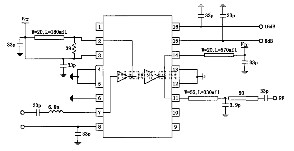
The circuit diagram illustrates the application of a 915MHz RF2155 power amplifier. The radio frequency (RF) signal enters through pin 7, where it is processed by a preamplifier. The output from the preamplifier is further amplified by the power...