
ssl3250a photo flash led driver circuit

The SSL3250A is a versatile integrated circuit designed for LED driving applications, particularly in portable devices. It operates over a wide input voltage range, making it suitable for various battery types and configurations. The ability to deliver a large maximum output current ensures that it can drive high-brightness LEDs effectively, which is crucial for applications requiring significant illumination, such as camera flash or torch functionalities.
The high efficiency of the SSL3250A is a key feature, as it minimizes power loss during operation, contributing to extended battery life. The soft-start functionality is particularly important in preventing sudden current surges that could damage the LED or the power source. This gradual ramp-up of current helps to ensure a smooth operation, particularly in sensitive applications.
In terms of protection features, the SSL3250A is equipped with several mechanisms to enhance reliability. Overvoltage protection prevents damage to the LED and the circuit in scenarios where the input voltage exceeds safe levels. Over-temperature protection ensures that the device operates within safe thermal limits, which is critical for maintaining performance and longevity. Feedback short protection and under-voltage lockout features further enhance the robustness of the design, preventing operational failures under adverse conditions.
The dual control modes—Direct and I2C—provide flexibility in how the SSL3250A can be integrated into a system. Direct control mode allows for straightforward implementation, where the device can be controlled using simple enable signals (EN1 and EN2). This mode is ideal for applications that require minimal complexity and quick response times.
On the other hand, I2C control mode offers advanced configurability, allowing for dynamic adjustments to timing and current settings. This mode is particularly beneficial in applications where different LED modes (Flash, Torch, Indicator) are required, enabling a single device to serve multiple functions based on the operational context. The use of I2C communication facilitates easy integration into microcontroller-based systems, allowing for more sophisticated control schemes.
Overall, the SSL3250A is designed to meet the demands of modern mobile applications, combining efficiency, protection, and versatile control options to ensure optimal performance in LED driving tasks.This device ensure a lot of implementation possibilities because it has wide input voltage range and the large maximum output current at a wide output voltage range. It has long battery life and low power strain because of it`s high efficiency and soft-start. This device has many features which is can be used to protect the battery and LED from ov erloading, and result in trouble-free operation of the whole mobile application such as overvoltage, over temperature and feedback shorted protection, under voltage lockout and time-out function. This is the figure of the circuit; This device (SSL3250A) has two general control modes: Direct control (the lower circuit schematic diagram) and I2C Control (the upper circuit schematic diagram).
The IC is designed to be directly controlled by the application in direct control mode. To change the timing and current settings of the SSL3250A, we can use I2C control. We can also use I2C control to switch the driver to Flash mode, Torch mode or Indicator mode. EN1 and EN2 are used in Direct control mode. SCL, SDA, and STRB are used in I2C control mode. In a typical application, we only allowed to use one control mode. 🔗 External reference
Related Circuits

The power supply circuit features a step-down capacitor (C1), bleeder resistors (R), a Zener diode (VS), a full diode (VD), and a filter capacitor (G), along with switches and batteries (GB, SC). The light control circuit is composed of...

Both circuits can synchronize trapezoidal wave voltage, which is converted into intermittent small rectangular pulses. Its working principle involves periodic operation in synchronization with the grid frequency of the zero-volt switching voltage of the DC chopper. Due to the...
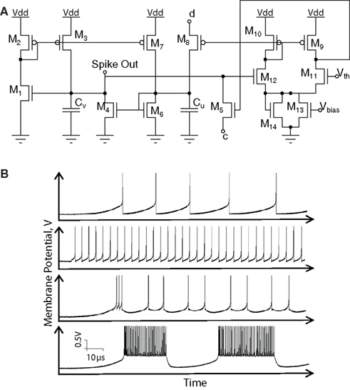
Hardware implementations of spiking neurons are highly beneficial for various applications, including high-speed modeling of large-scale neural systems, real-time operating systems, and bidirectional brain-machine interfaces. The specific circuit solutions for silicon neurons are dictated by the requirements of each...
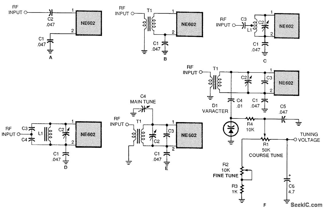
There are several methods to input a signal into the NE602. Simple untuned approaches (a and b) are viable. For tuning to a specific frequency, an LC resonant circuit with ungrounded trimmer capacitors (c and d) or grounded variable...
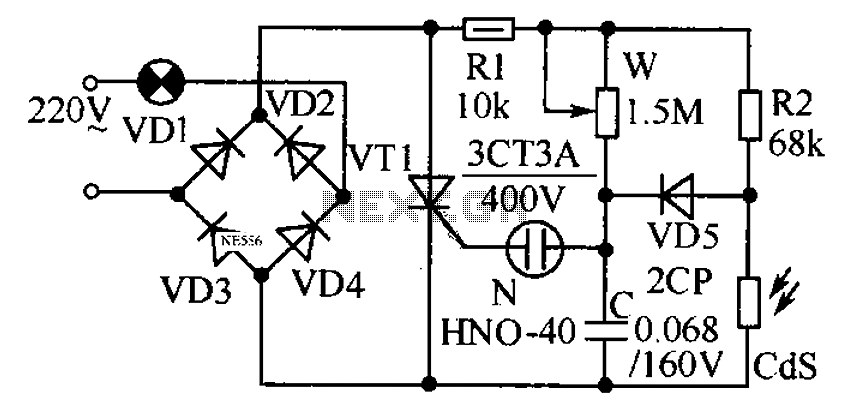
This circuit is designed to automatically adjust the brightness of lights based on the ambient light intensity. In bright conditions, the lights remain off, while in low ambient brightness, the lights are activated. The circuit incorporates a thyristor (VT1)...
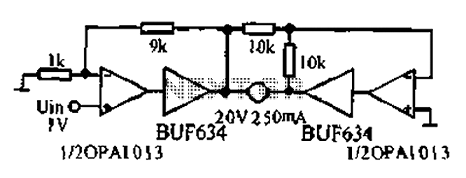
A bridge motor drive circuit is illustrated, featuring a driving stage composed of four transistors. The control circuit includes four terminals labeled A, B, C, and D, which facilitate the control of forward or reverse motor rotation. The control...