
Battery capacity / Accumulator Charge Meter
Stream from the output OUT is charged capacitor C is connected to a known timer 555th Reaches the voltage on the capacitor 2 / 3 power, turning it upside down to flip the timer circuit and the capacitor is quickly discharged transistor internal timer for 1 / 3 voltage. Then, the internal flip-flop timer tilted back and the capacitor can charge back the current flowing from pin OUT circuit MAX471. Since the rate of charging a capacitor is directly proportional to charging current, the output frequency proportional to the measured current.
Total connection counter is in Figure 2 Let's go back to the transmitter. According to catalog data conversion accuracy of current in the circuit deteriorates rapidly at low currents. This is probably caused by the output OUT is still a small stream flows. In my case, this current around 0.6 mA, which would correspond to the measured current 1.2 mA. When measuring current 12 mA residual current that would cause an error of 10%. The measured error, however, was considerably smaller, rather it seems to diminish the output current is below a certain threshold. Compensation of the current circuit is achieved with a transistor T3, diode D4, and trimmer P3, allowing for adjustment of the compensation current to significantly reduce the measurement error at low currents.
The conversion ratio of current in the circuit MAX471 is fixed, but the frequency can be adjusted by varying the capacitance of capacitors C4 and C5, which are connected in parallel to achieve the desired capacitance value. The trimmer P2 is used to fine-tune the frequency to an accuracy of 5%. For instance, when measuring a current of 100 mA, the counter should register 100 pulses per hour, necessitating an output frequency of 0.02778 Hz. To facilitate this, a frequency divider circuit, realized with a 4020 IC, is employed to enable easier measurement of the current.
The counter circuit utilizes a 4033 IC, which integrates a decimal counter and a decoder for a seven-segment display. The configuration allows for effective display of the measured values while minimizing the number of resistors required. Transistors T4 and T5 are used to manage the voltage levels on the display segments, with a potentiometer P4 allowing for adjustment of the display brightness.
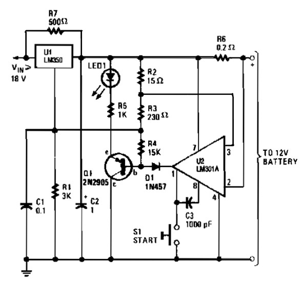
The operational management of the meter circuit is initiated by pressing the reset switch SW1, which initializes the counter and other components. Upon pressing the "start" button, the load is connected, and the measuring process commences. The comparator IC2a monitors the load voltage, and if it exceeds a predetermined threshold, it will stop the discharge process when the battery voltage falls below the set limit.
The device is designed for ease of assembly, utilizing a single-sided PCB with a mix of conventional and SMD components. The assembly process includes careful preparation of the PCB, installation of components, and adjustments to ensure proper functioning. Calibration of the device involves verifying the output voltage and frequency against known values, allowing for accurate measurements of battery capacity across different battery chemistries.
The parts list includes various resistors, transistors, diodes, integrated circuits, and capacitors, providing a comprehensive set of components necessary for the construction of the battery capacity meter. The device is capable of measuring discharge currents up to 3 A, with an accuracy of up to 5% for currents ranging from 0.01 to 3 A, making it suitable for a variety of battery types including Li-ion, NiCd, NiMH, and lead-acid batteries.The instrument used to measure battery capacity. The battery may be charged to any current in the range 0-3 A. The load current may be constant, may change over time or even break off completely. Unloading stops when the battery voltage drops below the set limit. Measuring the battery at various discharge currents, we consider the purpose for which it can still be used. Meter is based on the current-frequency converter. The output pulses of the converter are counted in counter, whose contents are displayed on the screen.
The appropriate choice of transfer constants are displayed directly passed through the hub size. For example, a current of 1 A for 1 hour with loads of pulses 1000. However, if diminishing current to 100 mA, the output frequency is 10 times lower transmitter and pulses will be only one hundredth To read in Pulse 1000, the same as in the previous case, the converter would have to pass through stream 10 times longer. For practical reasons, however, given the current transmitter frequency several orders of magnitude higher and the required number of pulses per unit time decreases divider.
We do not have to monitor battery voltage, the meter is completed circuit, which disconnects the load is reduced when the voltage is below the set limit. Involvement of the current-frequency converter is in Figure 1 The converter circuit using MAX471, which is designed to monitor the battery charge in portable devices.
Monitored current passes between the pin RS + and RS-circuit. The current creates a voltage drop across the internal resistor with resistance of about 35 milliohms. The voltage drop is in the direction of current flow amplified by the amplifier A1 or A2 and is employed by one of two sources of power transistors Q1 and Q2.
Their outputs are combined and connected to a common outlet OUT. From this flows the outlet stream, which is in absolute value 2000x smaller than the current passing between the terminals + and MS-MS. Voltage outputs of amplifiers A1 and A2 control comparator. The output (pin SIGN) is a logic level indicating the direction of current flow - sign. Indication of the direction of flow meter is not used, only the expected battery. Stream from the output OUT is charged capacitor C is connected to a known timer 555th Reaches the voltage on the capacitor 2 / 3 power, turning it upside down to flip the timer circuit and the capacitor is quickly discharged transistor internal timer for 1 / 3 voltage.
Then, the internal flip-flop timer tilted back and the capacitor can charge back the current flowing from pin OUT circuit MAX471. Since the rate of charging a capacitor is directly proportional to charging current, the output frequency proportional to the measured current.
Total connection counter is in Figure 2 Let's go back to the transmitter. According to catalog data conversion accuracy of current in the circuit deteriorates rapidly at low currents. This is probably caused by the output OUT is still a small stream flows. In my case, this current around 0.6 mA, which would correspond to the measured current 1.2 mA. When measuring current 12 mA residual current that would cause an error of 10%. The measured error, however, was considerably smaller, rather it seems to diminish the output current is below a certain threshold.
I decided to compensate the current circuit with a transistor T3, diode D4 and trimmer P3. I of course setting the compensation current can significantly reduce the measurement error at low currents. For completeness, according to the catalog data may be OUT pin leakage current to 2.5 mA (10% error at 50 mA).
Another problem is setting the correct conversion ratio. The conversion ratio of current in the circuit MAX471 can not change. Roughly the frequency is set condenser capacity. Since the capacitors are normally sold only in E6 and a tolerance of 10%, it is possible to obtain the required capacity of the parallel connection of capacitors C4 and C5. Thus it is appropriate to adjust the frequency to an accuracy of 5%. Then gently set the trimmer P2. When measuring current of 100 mA is needed to bring the counter to 100 pulses per hour. The output of the converter, in this case had to be 0.02778 Hz frequency. Such a rate would be set up during the measuring device rather difficult, notwithstanding the fact that the capacitor in the transmitter would have a capacity of about 1,000 mF with a negligible leakage current.
So I have a significantly higher frequency and the transmitter followed by two divider 14 , the circuit realized 4020th Frequency converter for adjusting easily measure the current counter (measuring frequency) converter and a capacitor foil may be good, because it has a positive capacity of around 58 nF. To use my own counter circuits 4033, associating decimal counter and a decoder for the seven-segment display with common cathode.
Unlike more familiar circuit 4026 differs only by the absence of independent output segment "c" to allow to participate as a divider circuit 6 (in hours) and the extinction of the screen. Circuit 4033 is, however, leads RBI and RBO, which can suppress the concatenation minor scratch from measured data.
Each segment display decoder normally connected via current-limiting resistors. Before I used a large number of resistors, I used a better circuit with transistors T4 and T5, which can change the voltage on the cathodes of the displays, and LCD segments connected directly to the IC. Potentiometer P4 to change voltage from 0.5 to 3 V and current segments from 5 to 0.2 mA. Now it should be noted in the management of the meter circuit. Sw1 After pressing the "reset" (and also when the power supply) with the entry gates will IC1b level L, at the output level of H.
This resets the counter circuit IC9 and IC6 IC5 and frequency divider. Despite IC1a the gate trigger circuit of the gate IC1c IC1d and put into a state in which the level on pin 10 and pin L 11 H level LEDs are lit and a comparator having an output transistor IC2b closed. Enclosed is also a transistor T1 and T2. The load voltage is zero. This reverses IC2a ??comparator, the output transistor is opened and maintained at the input level L IC1d (pin 13).
Through the diode D3, capacitors to maintain low C4 and C5, which blocks the converter. Connect the battery and the load measured. After pressing "start" at the exit gate level appears IC1c H. unlocks the converter (diode D3) IC2b comparator reverses and opens the transistors T1 and T2. The load current is now: in positive strand through MAX471 circuit, the negative through the transistor T2. The burden will be tension watch IC2a ??comparator. If the load voltage greater than the set switch, or potentiometer P1, the comparator reverses IC2a ??and its output transistor is closed.
At the entrance gate IC1d - pin 13 will be level H, the output (pin 11) Level L and lights LED1. IC1c gates and flip-flop IC1d form of MS. Condition at the output is maintained even after the button "Start". Discharged if the battery is below the set voltage, the comparator reverses IC2a ??and retrieve its output to the input level IC1d L. This circuit reverses MS LED1 goes off and disconnects the load. The display will remain lit last loaded condition. Now we have two options. You can either click the "reset" to reset the counter to prepare the instrument for another measurement, or change (reduce) the burden and the "Start" button to continue the measurement.
The load can be changed at any time during the measurement. The only condition is that the constant current circuit MAX471 no larger than 3 A. Sensing resistor in the circuit MAX471 associated with positive voltage. Then it would be virtually impossible to open the transistor T2 from a positive voltage of +5 V, where we measured nearly dead battery with a voltage just above 0.9 V. It is open to the transistor T2 stabilized positive voltage applied to at least 3 more. IC2b comparator, the transistor T1 and other components are in fact only the voltage level converter.
The battery voltage monitor comparator IC2a. Divider R5, R6 and R7 creates a voltage drop of about 0.455 V at the resistor R5. The voltage comparator compares the voltage divider R8-R11 and P1. The switch can be selected using the set voltage divider for 0.9 and 3.3 V or division ratio set by potentiometer P1. Comparator reference voltage is derived from a supply voltage of +5 V. Therefore, this voltage must be set accurately and fairly stable. It's very clear connection, because the stabilizer is powered and the display, but in practice had been met.
Battery capacity meter is based on one-sided PCB, equipped with conventional and SMD components. In all SMD resistors, blocking capacitors and "small" transistors. Users can also SMD transistor T5, the diode D5 and capacitor C3. Greater involvement of the complexity of the required nine wire jumpers, and in some places through the joints between the IC pins. Before the installation of components in the slab first be carefully prepared. Drill all necessary holes and possibly opilujte so that they fit seamlessly into the box. Fit of the first SMD connections and then classical components, potentiometers and switches. The connection terminals of potentiometers use a thin plate with tinned wire. If you prefer, you can be fitted into the IC sockets. MAX471 circuit in the base may be, it must be soldered directly to the board. Contact resistance sleeve could cause uneven distribution of current between terminals 2 and 3, respectively.
6 and 7 After the installation of devices connect the power supply via an ammeter. The supply voltage is greater than 8 V should display some light reading (probably 0) and its luminosity should be given control potentiometer P4. Measuring the voltage to 5 V. Compared to the common wire should not be measured variations greater than 20 mV. Due to tolerances sold LM317 circuit, you'll probably need to connect to R22 or R23 resistor in parallel with an appropriate resistance so that the voltage was as close to +5 V solder pads for the resistors on the board already in place.
In my case I had to connect the 22 Ohm resistor in parallel with R23, without the supply voltage is nearly 5.2 V. If you set the power supply, connect a regulated power supply instead of battery. Hold down the "start" and gradually change the voltage source. The actual switching voltage so you know, it just turns on (or Off) LEDs. Check the power voltage of 0.9 and 3.3 V, the same way you can even brand the scale of the potentiometer P1.
Set the conversion remains constant and current compensation. Instead leave the battery connected to a source or a battery. Reverse jumper JP1 to position test. Start the timer. Even without a load attached to the counter add to figures pulses caused by residual current circuit MAX471. Connect the load to the meter so that the discharge current was in the range of 0.1 to 1 A. The Measure as accurately as possible discharge current. Measured magnitude of the current in mA multiplied by a constant 4.5511. The result is frequency in Hz, which we have measured at pin 3 of timer 555 or the passage of the test position.
Eg. current of 100 mA should be frequency 455.11 Hz. If the frequency is significantly different, adjust the capacity of a combination of C4 and C5. The lower frequency deviation tune trimmer P2. Reduce the load so that the discharge current was only 10 to 20 mA. Measure the frequency and adjust the trimmer P3 so that the measurement error is minimized. If necessary, you can also adjust the power supply firmly set. Changing the voltage of 0.9 V for NiCd and NiMH batteries may not be meaningful because the battery voltage at the end of discharge decreases rapidly, and results will vary little. Voltage 3.3 V I chose with regard to the specific use of Li-ion battery. For the switching voltage of 2.7 V should be adjusted resistors R10 and R11 so that their sum was about 18.5 Ohm, for 3 in the approximately 21.5 kOhm.
If you need to set a voltage greater than 10V, use the P1 with greater resistance. Return JP1 to position measurements. This device is electrically configured and ready for use. PCB I built the box KP5 from which it is necessary to remove the corner pins. The upper and lower parts are then combined distance column in the middle of the box. The gap between the upper and lower part is slightly larger than 20 mm. To cover the tightening neprolomilo, it should still post substantiate 2-3 pads. To use the power adapter from the charger to drill. Output load voltage adapter is about 25 V, the load current of 150 mA is about 22 V. With such a large supply voltage can be adjusted to maintain maximum shine display, because the stabilizer is overheating. For full brightness it is necessary to use less power (8-12 V) or a stabilizer to provide a cooler. End The meter I have successfully used for classifying the Li-ion batteries from discarded cell phones.
Wear in these accumulators is manifested mainly by increasing the internal resistance of cells. When a large current discharge capacity of the small, but as for powering devices with even a small donation is made. The apparatus can also measure the capacity of NiCd, NiMH, alkaline and lead acid gel. The advantage is that you can measure battery capacity in a particular application, because the load may serve as a device that is battery powered then.
Parts List R1, R3, R17 1 MW, SMD 1206 D1 to D4 1N4148 SMD R2, R4, R18 100 kW, SMD 1206 D5 1N4007, SMD or DO41 R5 470 W, SMD 1206 ZD 16 V Zener diode SMD BZV55C16 R6 2 kW, SMD 1206 T1, T2 BC856B R7 2.7 kW, SMD 1206 T3 BC847C R8, R9, R21 4.7 kW, SMD 1206 T4 IRLZ34N R10, R12, R13, R15, R19 22 kW, SMD 1206 T5 Or BCP68 BC639-25 R11, R16 2.2 kW, SMD 1206 IC1 CMOS 4093 R20 3.9 kW, SMD 1206 IC2 LM393 R22 330 W, SMD 1206 IC3 MAX471CPA R23 1 kW, SMD 1206 IC4 TS555 P1 100 kW potentiometer PC1222NK100 IC5 CMOS 4020 P2 10 kW Trimmer PT6VK010 IC6 and IC9 CMOS 4033 P3 100 kW Trimmer PT6VK100 IC10 LM317K P4 5 kW potentiometer PC1222NK005 LED1 LED low wattage red C1, C2 33 nF, SMD 1206 O1, O2 HDSP-K123 C3 1 uF SMD or subminiature SW1, SW2 button DT6 C4, C5 together about 58 nF, see text Foil spacing RM = 5 mm SW3 3-position slide switch C6a C10 100 nF, SMD 1206 K1 power outlet SCD-016 PCB bcs48 Box KP5 power wires and alligator clips Discharge current: Discharge Current: up to 3 A. Accuracy: Measure error: up to 5% in the current / current at 0.01 to 3 A. Range: Measure range: 0 and / is 9999 mAh. Battery power: Accumulator Voltage: up to 50 V. Unloading is completed in tension: Gischarging terminate Voltage: 3.3 V or 0.9 V Selectable / Cluster 0.9 and / to 10 V.
Power supply unit: Supply Voltage: 8 to / to 25 V. Supply current: Supply current: 10 to / a 150 mA (according to the brightness of the screen / display of bright depend ). 🔗 External reference
Related Circuits
The gelled lead-acid battery charger circuit diagram enables rapid charging of gelled lead-acid batteries and automatically shuts off upon reaching full charge. Initially, the charging current is maintained at 2 A; however, as the battery voltage increases, the current...
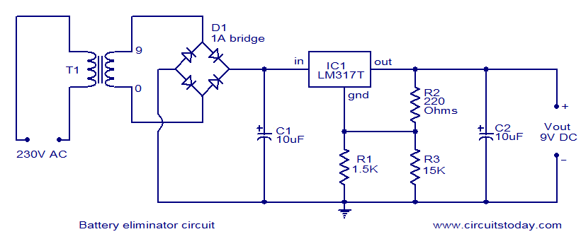
This document presents a circuit diagram of a battery eliminator circuit designed to replace 9V PP3 batteries. It can power any device that operates on a 9V battery. The transformer T1 reduces the mains voltage, while bridge rectifier D1...
A VU-meter is a common instrument typically found on audio Hi-Fi amplifiers, designed to display the instantaneous power delivered to the speakers. It is usually connected at the amplifier's output, in parallel with the speaker. The term "VU" stands...
This Class E RF amplifier is capable of delivering up to 400 watts of RF output, depending on the input voltage and tuning parameters (current). The amplifier employs economical IXDD414 Driver ICs, with one driver for every two MOSFETs....
Temperature sensor converter designed for use with a digital multimeter, capable of measuring temperatures from -40 °C to 110 °C. It features a state indicator and requires no calibration, utilizing the LM35 integrated circuit. The freezing point of water...
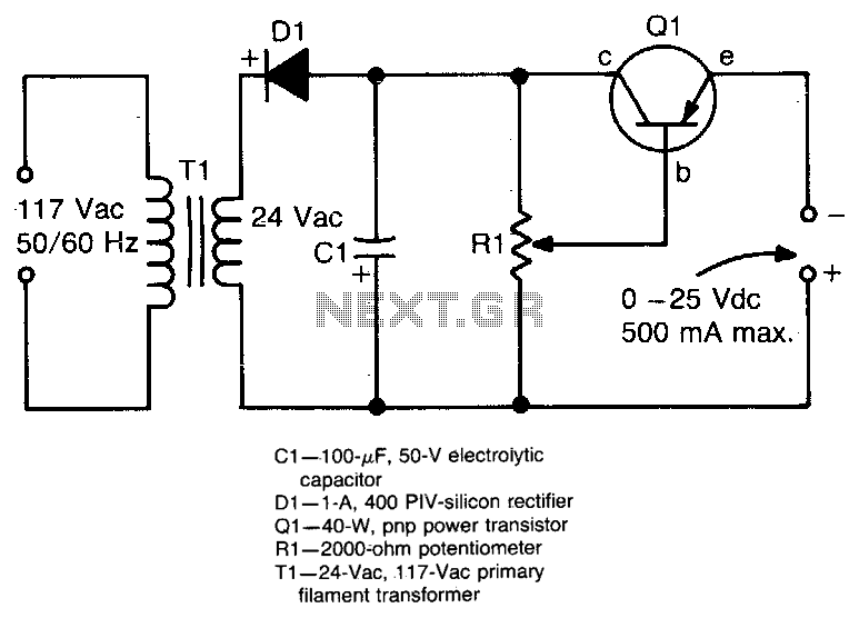
This circuit provides an adjustable output voltage of up to 35 V DC with a maximum output current of 50 mA. The transistor Q1 dissipates significant heat and must be mounted on a heatsink. The circuit in question is designed...