
Simple ni-cad battery charger

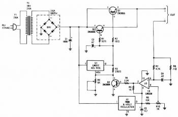
The circuit in question is designed to deliver a regulated output voltage that can be adjusted within the range of 0 to 35 volts DC, making it suitable for various applications requiring a stable power supply. The maximum output current is specified at 50 mA, indicating that the circuit is intended for low-power devices.
At the core of this circuit is transistor Q1, which plays a crucial role in voltage regulation. The choice of transistor is critical, as it must handle the power dissipation effectively. Given that Q1 dissipates considerable heat during operation, it is essential to attach it to a heatsink. The heatsink will aid in dissipating the heat generated, thereby preventing thermal overload and ensuring reliable operation.
The adjustable output voltage feature is typically achieved using a potentiometer or a variable resistor connected to the base of the transistor. This setup allows for fine-tuning the output voltage according to the specific requirements of the load. Additionally, the circuit may include feedback mechanisms to stabilize the output voltage against fluctuations in load current or input voltage.
To ensure optimal performance, it is recommended to use a transistor with a suitable power rating and thermal resistance. The heatsink should be chosen based on the thermal characteristics of the transistor and the expected ambient temperature to maintain safe operating conditions.
Overall, this circuit is a versatile solution for applications needing adjustable voltage levels, with careful consideration of thermal management to enhance reliability and efficiency.This circuit provides an adjustable output voltage up to 35 Vdc and maximum output current of 50 mA Transistor Ql dissipates quite a bit of heat and must be mounted on a heatsink.
Related Circuits
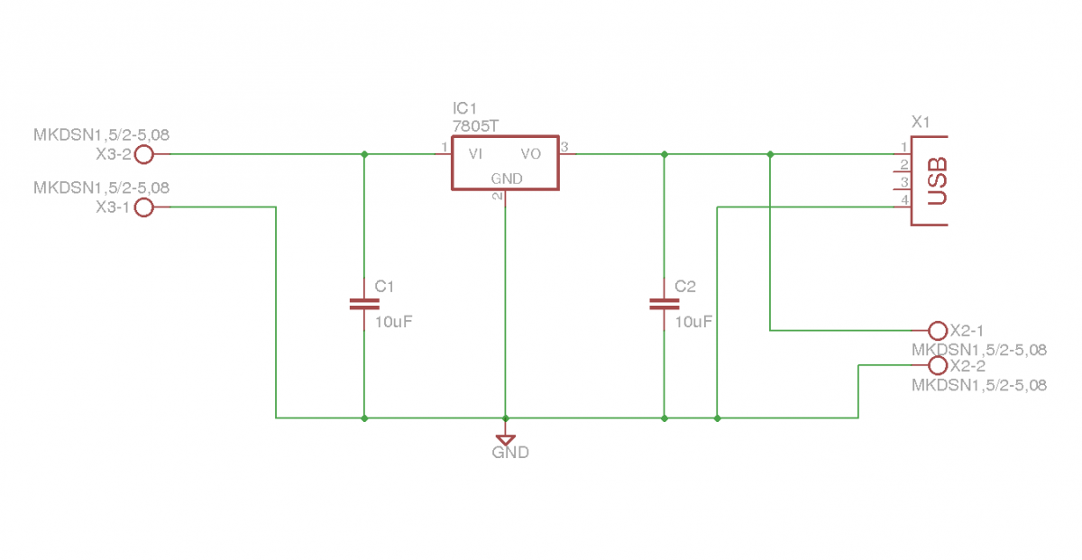
This document outlines the details of several circuits designed and built for a robot. The first circuit is a voltage regulator intended to supply power to a Raspberry Pi from a 7.2V battery. While the circuit is relatively simple,...
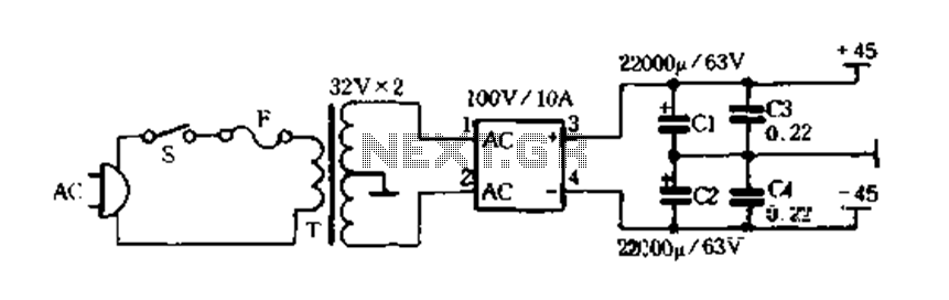
The charger is capable of charging a single cell or multiple series-connected cells with a maximum voltage of 18V. Power transistors Q1 and Q2 are configured as series regulators to manage the output voltage and charging current of the...
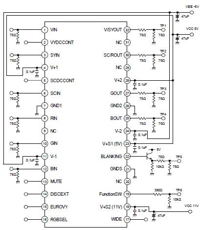
A straightforward 4-channel video amplifier electronic circuit can be constructed using the NJM2582 integrated circuit, which is suitable for video applications with a SCART connector. The design of this circuit is uncomplicated and requires only a few external electronic...
The differential input stage utilizes the integrated differential transistors 2SC1583 and 2SA798, with the amplified signal directed to the power amplifier tubes VT5 and VT6. The performance of the charge directly influences the overall performance of the power amplifier...
Ambient light is increasingly being utilized as an energy source. To assist designers in developing such systems, this circuit effectively measures ambient light intensity across four decades of measurement. The design is cost-effective, and with the sensor housed in...
This is a simple NiCd battery charger powered by solar cells. A solar cell panel or an array of solar cells can charge a battery at more than 80% efficiency, provided the available voltage exceeds the fully charged battery...