
Battery charger

The described circuit employs a diac in conjunction with a triac to control power delivery in AC applications. The diac functions as a switching device that allows current to flow only after a specific voltage threshold is reached, effectively controlling the gate of the triac. R1 is crucial as it determines the firing threshold of the triac; once the voltage across R1 exceeds this threshold, the diac conducts, triggering the triac and allowing current to flow through the load.
C3 and R4 are integral components of the transient suppression network, designed to protect the circuit from voltage spikes that may occur during operation. C3 acts as a filter capacitor, smoothing out any rapid changes in voltage and preventing unwanted triggering of the triac. R4 serves to limit the maximum charging current to C3, ensuring that the capacitor charges within safe limits and preventing damage to the circuit.
The phase-shift network composed of R1, R2, R3, C1, and C2 is essential for controlling the timing of the triac's firing. This network introduces a phase shift in the input signal, allowing for precise control over the power delivered to the load. The values of R2, R3, C1, and C2 can be adjusted to modify the phase angle, thus influencing the timing of when the triac is triggered during each AC cycle.
Overall, this circuit configuration is commonly found in light dimmers, motor speed controls, and other applications requiring phase control of AC loads. The combination of the diac and triac, along with the supporting components, enables efficient and reliable control of power in various electronic applications.A diac is used in the gate circuit to provide work for the signal being applied to the gate. R1 a threshold level for firing the triac. C3 and R4 is selected to limit the maximum charging cur-provide a transient suppression network Rl, rent at fullTotation of R2. R2, R3, Cl, and C2 provide a phase-shift net-.
Related Circuits
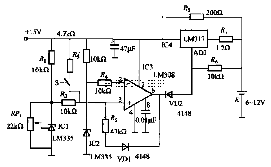
When fast charging a nickel-cadmium battery, the temperature control circuit, as illustrated in the accompanying figure, is designed to monitor the battery temperature to regulate the charging current. The circuit consists of Icl to IC3, which forms the temperature...
The circuit is designed for charging NiMH batteries using the MAX712 integrated circuit (IC), which provides all necessary functionalities for controlled charging. The schematic of the charger is centered around IC1, the MAX712 from Maxim, which comes in a...
Charger for car battery power supply. Refer to the webpage for an explanation of the power supply-related circuit diagram. The battery charger indicator circuit described above enhances the appearance of a simple battery charger. This circuit serves as a...
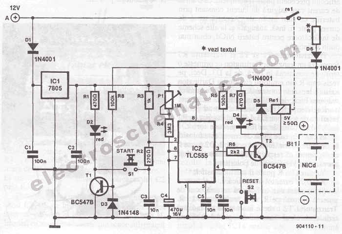
The portable battery charger has been designed to enable the charging of NiCd batteries outdoors using a 12 V vehicle battery. The portable battery charger is engineered to facilitate the charging of Nickel-Cadmium (NiCd) batteries in outdoor environments, leveraging the...
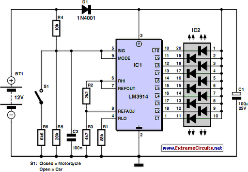
Camping today often requires various electronic devices for daily activities and entertainment. Typically, a charged lead-acid battery and a power inverter are utilized to ensure a well-organized trip, allowing family members to enjoy their electronic equipment. It is essential...
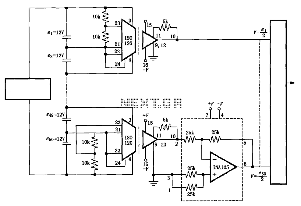
The circuit utilizes the ISO120 and INA105 instrumentation amplifiers to create a battery monitoring system for a 600V battery setup composed of 50 series-connected 12V batteries. This circuit is designed to detect charging and discharging conditions to prevent overcharging...