
Car and Motorcycle Battery Tester

This circuit is designed to provide a straightforward and efficient method for monitoring the voltage levels of lead-acid batteries commonly used in camping and motorcycle applications. The LM3914 integrated circuit serves as the core component, which is a voltage level indicator that can drive multiple LEDs to visually represent the battery's state of charge. The circuit configuration includes a power supply section that connects to the battery being tested, either a 12V or 6V, depending on the switch position.
The use of switch S1 allows the user to easily toggle between battery types, ensuring accurate readings. When the circuit is powered on, the LM3914 receives the battery voltage and lights up the corresponding LEDs based on the voltage level detected. The top LED activation indicates that the battery is fully charged, which is an essential feature for users who rely on these batteries for their electronic devices during camping trips.
The inclusion of diode D1 is crucial for protecting the circuit from potential reverse voltage situations, which could damage the LM3914. This precaution ensures the longevity and reliability of the circuit during its use. The option to implement a color-coded display with individual LEDs provides a more intuitive way to assess battery status, as users can quickly identify the battery condition at a glance.
Overall, this circuit provides a practical solution for campers and motorcyclists to monitor their battery levels effectively, ensuring that they can enjoy their electronic devices without the worry of battery depletion. Its simplicity and low power consumption make it an ideal companion for outdoor adventures.Going camping nowadays involves taking lots of electronic equipment whether for day to day running or for fun and entertainment. Most of the time a charged lead acid battery and a power inverter would be used to ensure a smoothly organized holiday where ideally the missus and the children cheerfully use their electric and electronic gear!
With rec hargeable lead-acid batteries it`s invariably useful - if not essential - to determine whether the power source you`re hauling along on your travels is losing capacity and needs to be topped up. The same circuit would also come in handy when going on a car or motorbike trip as it can check the status of a 12 V (car) or a 6 V (motorcycle) battery.
Although the circuit draws so little power that it will not noticeably load the battery under test, it should not be left connected permanently. The circuit employs the familiar LM3914 (IC1) to display the voltage level. The LED readout creates a battery status readout: when the top LED lights, the battery is fully charged.
When the bottom LED lights, the battery needs imminent charging! Switch S1 selects between 12 V and 6 V operation. A series diode, D1, protects the bargraph driver from reverse supply voltage. A color-coded display with individual LEDs could be used instead of the common-anode bargraph display for better indication of the state of the battery. 🔗 External reference
Related Circuits

A small and portable unit that can be assembled on a veroboard. Mobile phone chargers available in the market are quite expensive. The circuit presented here comes... The described circuit is a compact and cost-effective mobile phone charger designed for...
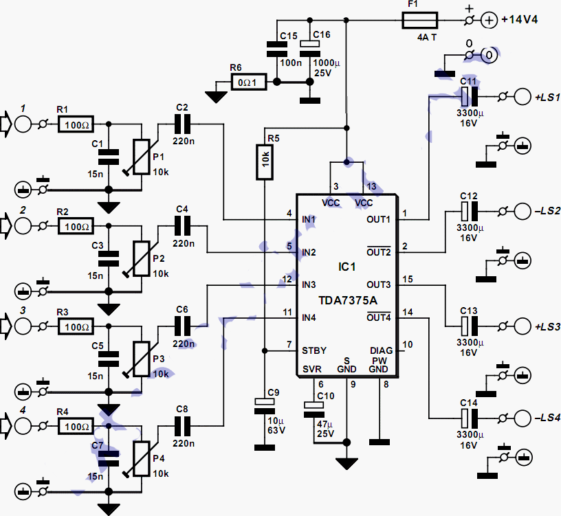
This quad amplifier is designed primarily for automotive use but can also be applied in various medium-power scenarios. The TDA7375A is suitable for situations requiring a reasonable amount of audio power with a relatively low supply voltage. It is...
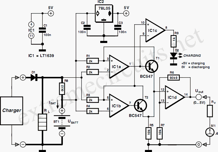
The Over-the-Top type of operational amplifier is ideal for use as a current sensor for battery charger applications. The design described here can be used with chargers for rechargeable batteries (Lead/acid or NiCd, etc.). The 5 V operating supply...
The following demonstrates a power-saving circuit that pulses a sensor for 1 second every 30 minutes. It is designed to monitor the levels of salt. The sensor shown is an optocoupler with an infrared-emitting diode, intended to monitor the...
This car stereo booster utilizes an LM2896 integrated circuit, which features two amplifiers. It operates with supply voltages ranging from 3 to 15 volts. The power output is 2.5 watts per channel when connected to an 8-ohm load at...
Schematic and description of a simple and easy-to-build NiCd and NiMH battery charger circuit that is capable of charging multiple NiCd and NiMH batteries. The circuit for the NiCd and NiMH battery charger is designed to be straightforward, allowing for...