
Battery charger circuit using LM317

The battery charger circuit using the LM317 is structured to provide a reliable and efficient charging solution for 12V lead-acid batteries. The LM317 is favored for its ease of use and versatility in voltage regulation, making it suitable for various applications, including battery charging.
The circuit's operational efficiency hinges on the correct selection and configuration of its components. The transistor Q1 plays a crucial role in regulating the output current and voltage. Resistor R1 is essential for limiting the current during the initial charging phase, preventing excessive current that could damage the battery. The inclusion of potentiometer R5 allows for fine-tuning of the charging voltage, enabling the user to set the output voltage according to the specific requirements of the battery being charged.
When the battery is connected, the initial current flow through R1 leads to an increase in the output voltage from the LM317, which is sensed by the battery. As the battery charges, the voltage across it rises, and once it reaches a predetermined level, the LM317 reduces the output current. This automatic adjustment is critical for maintaining the health of the battery, as it prevents overcharging, which can significantly reduce battery lifespan.
The design requires an input voltage that exceeds the output voltage by at least 3V to ensure proper regulation by the LM317. This voltage drop is a characteristic of the LM317, and it is essential to account for it when selecting the power supply. The choice of an 18V DC input is appropriate, providing sufficient headroom for the LM317 to operate effectively while delivering the required charging voltage to the battery.
Overall, this LM317-based battery charger circuit is a practical solution for charging lead-acid batteries, combining simplicity with functionality. Its design allows for easy assembly and adjustment, making it accessible for hobbyists and professionals alike.Here is a simple but effective battery charger circuit using IC LM 317. The circuit can be used to charge 12Vlead acid batteries. The circuit is very simple and can be easily assembled on a general purpose PCB. The heart of the circuit is IC LM 317, which is an adjustable voltage regulator IC. The pin 1 of the IC is the control pin which is used to c ontrol the charging voltage. The pin 2 is the output pin at which the charging voltage appears. The pin 3 is the input pin to which the regulated DC supply is given. The charging voltage and current is controlled by the Transistor Q1, resistor R1 and POT R5. when the battery is first connected to the charging terminals, the current through R1 increases. This in turn increases the current and voltage from LM 317. When the battery is fully charged the charger reduces the charging current and the battery will be charged in the trickle charging mode. The input voltage to the circuit must be atleast 3V higher than the expected output voltage. LM 317 dissipates around 3V during its operation. Here I used 18V DC as the input. 🔗 External reference
Related Circuits
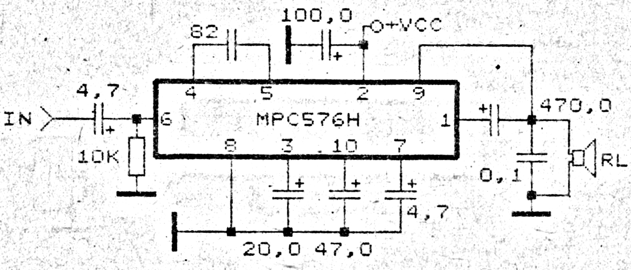
This amplifier circuit exhibits good sound quality. Although it does not provide high output power, it is capable of producing both soft and loud sounds reliably. The circuit utilizes a single IC, the MPC576H, along with several supporting components....

A small and portable unit that can be assembled on a veroboard. Mobile phone chargers available in the market are quite expensive. The circuit presented here comes... The described circuit is a compact and cost-effective mobile phone charger designed for...
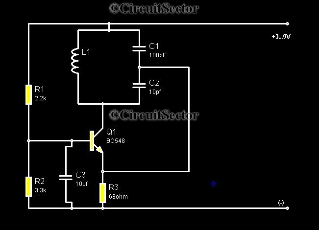
Metal detectors are typically complex devices that often incorporate expensive components, making DIY metal detector circuits uncommon. However, this metal detector hobby circuit can be built using only a few components, such as a BC548 transistor and a standard...
The AquaCont is an electronic system which permits to manage and to monitor most of the parameters of all the electric devices that can be found in an aquarium. The PIC18F4520 used to realize it combines a real-time clock...
This information pertains to a dosing pump control circuit that utilizes the LM317 integrated circuit (IC). The circuit operates with a power supply of 24V DC and is capable of adjusting the output voltage to 1.25V. The LM317 is a...
This fluid level sensor circuit is designed to use an AC sensing signal to prevent electrolytic corrosion on the probes. The rectified AC signal is utilized to drive a T1 transistor, which in turn activates a 12-volt relay that...