
Mobile Phone Battery Charger

The described circuit is a compact and cost-effective mobile phone charger designed for assembly on a veroboard. This design allows for easy customization and prototyping, making it suitable for electronics enthusiasts and engineers alike.
The circuit typically incorporates a voltage regulator to ensure that the output voltage matches the requirements of various mobile phone models. Commonly used components may include a 7805 voltage regulator, which provides a stable 5V output, suitable for charging most mobile devices.
Additionally, the circuit may feature input protection components such as diodes to prevent reverse polarity and ensure safe operation. Capacitors are often included at the input and output of the voltage regulator to filter noise and stabilize the voltage, enhancing the performance of the charger.
For efficiency, a switching regulator could be employed instead of a linear regulator, which would reduce heat generation and increase overall energy efficiency. The design could also incorporate a USB output for compatibility with standard charging cables, allowing for widespread usability.
Moreover, the circuit can be powered from a variety of sources, including wall adapters or solar panels, making it versatile for different applications. The use of a veroboard for assembly provides flexibility in component placement and circuit modifications, allowing users to adapt the charger to meet specific needs or to integrate additional features such as LED indicators to show charging status.
This mobile phone charger circuit is an excellent project for those looking to understand power management in electronics while providing a practical solution for charging devices economically.Small and portable unit, Can be assembled on veroboard Mobile phone chargers available in the market are quite expensive. The circuit presented here comes.. 🔗 External reference
Related Circuits
A DIY GSM jammer schematic diagram designed for use with GSM1900, operating within the frequency range of 1930 MHz to 1990 MHz. The GSM jammer circuit is intended to disrupt communication between mobile phones and base stations within the specified...
To design a Tube Headphone Amplifier we need a triode with uncommon characteristics: enough voltage gain, low internal resistance and good anodic current. My first test was done with the E182CC, but there is the limitation on the usable...
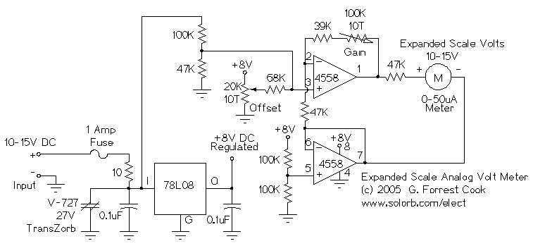
This circuit is used to measure the voltage on a 12V (nominal) lead acid rechargeable battery system. It was specifically designed for use in solar powered systems, but is general enough that it can be used for automotive or...
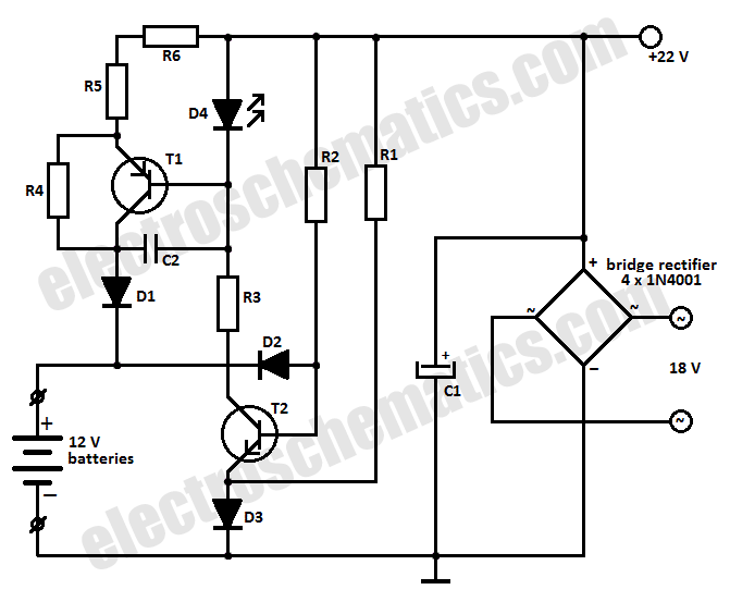
This battery charger circuit is designed to charge one or more batteries with a total nominal voltage of 12 V, which accommodates either ten NiCd batteries or six 2 V lead-acid batteries. The battery charger circuit operates by utilizing a...
This is a dry cell battery charger circuit designed to charge batteries over a period of approximately 12 hours. When powered by a 9-volt supply, the circuit is configured to accommodate AA-sized batteries. If C or D-sized batteries are...
This project originated from a design requirement for a client, specifically for a microphone preamplifier intended for basic public address (PA) systems. The simplicity of this circuit makes it suitable for various applications where a mic preamp is needed,...