
Battery charger with LM317
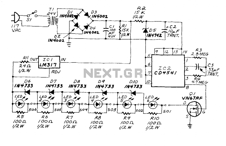
A timing circuit is implemented to prevent overcharging. Upon power application to the circuit, timing is initiated by IC2, a CD4541 oscillator/programmable timer. The output from IC2 is connected to Q1. When the output is high, the transistor is activated, completing the charging circuit. Conversely, when the output is low, the transistor is deactivated, interrupting the path to ground.
The circuit employs the LM317 voltage regulator, which is known for its versatility in providing stable output voltage and current regulation. In this configuration, it operates as a constant-current source, ensuring that a steady 50 mA is delivered to the battery holders, which is crucial for safe and efficient charging of the AA cells.
The LED indicators serve a dual purpose: they provide visual feedback on the charging status of each battery holder and also help in identifying whether a battery is present. The inclusion of shunt resistors is essential for limiting the current through the LEDs, preventing them from drawing excessive current that could lead to burnout.
The 5.1-volt Zener diodes parallel to the battery holders play a critical role in safeguarding the circuit. In scenarios where a battery holder is empty, the Zener diodes allow the current to bypass the holder, thus preventing potential damage to the charging circuit due to an open circuit condition. This design choice enhances the reliability of the charging system.
The timing mechanism, driven by the CD4541 timer IC, is a pivotal feature of the circuit. The timer can be programmed to establish a specific charging duration, thereby preventing overcharging of the batteries, which can lead to reduced battery life or even leakage. The transistor Q1 acts as a switch that controls the charging path based on the timer's output, ensuring that the charging process is automatically halted once the predetermined time has elapsed.
Overall, this circuit design effectively combines voltage regulation, current control, visual indication, and timing functionality to create a robust charging solution for AA-cell batteries, ensuring both safety and efficiency in the charging process.An LM317 voltage regulator is configured as a constant-current source. It is used to supply the 50 mA charging current to S01-S06, an array of AA-cell battery holders. Each of the battery holders is wired in series with an LED and its associated shunt resistor. When the battery holder contains a battery, the LED glows during charging. Each battery holder/LED combination is paralleled by a 5.1-volt Zener diode. If the battery holder is empty, the Zener conducts the current around the holder. A timing circuit prevents overcharging. When power is applied to the circuit, timing is initiated by IC2, a CD4541 oscillator/programmable timer. The output of IC2 is fed to Ql. When that output is high, the transistor is on, and the charging circuit is completed. When the output is low, the transistor is off, and the path to ground is interrupted. 🔗 External reference
Related Circuits
Protect expensive batteries from discharge damage with this mini-sized electronic cutout switch. It uses virtually no power and can be built to suit a wide range of battery voltages. The mini-sized electronic cutout switch serves as a crucial component in...
The first circuit is designed for discharging nickel-cadmium batteries before recharging to eliminate the "memory effect." After discharging, the power is automatically converted to the state of charge. The charging process utilizes pulse-width modulation for constant current, along with...
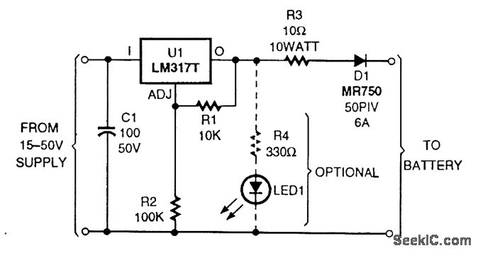
The circuit is based on an LM317T adjustable voltage regulator. The output voltage (VOUT) is defined by the formula VOUT = 1.25 (1 + R2/R1). A 10-kΩ resistor is selected for R1 and a 100-kΩ resistor for R2, allowing...
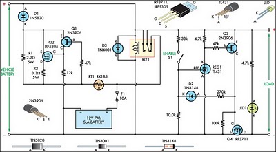
This circuit is designed to switch power to a Peltier cooler in a vehicle. Power is supplied to the load from the vehicle's battery when the ignition switch is on and from an SLA auxiliary battery when the ignition...
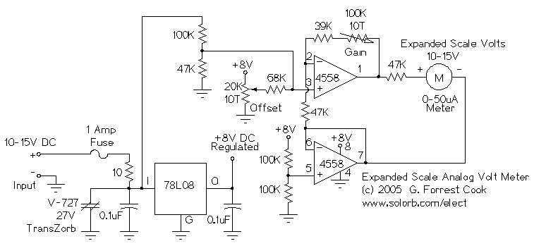
This circuit is used to measure the voltage on a 12V (nominal) lead acid rechargeable battery system. It was specifically designed for use in solar powered systems, but is general enough that it can be used for automotive or...
The ASUS Eee is an ultra-portable notebook designed for tech enthusiasts, offering essential features without unnecessary extras. It boasts excellent build quality and is competitively priced. In New Zealand, it can be purchased exclusively from DSE, making it cost-effective...