
BATTERY TRICKLE CHARGER

The LM317T is a versatile adjustable voltage regulator commonly used in power supply applications. The adjustment of the output voltage is achieved by varying the resistor values R1 and R2 in the feedback network. The chosen values of 10 kΩ for R1 and 100 kΩ for R2 provide a stable output voltage of 13.75 V, calculated using the formula VOUT = 1.25 (1 + R2/R1). This configuration allows for a small quiescent current, which is beneficial for battery-operated devices.
Incorporating a diode in the circuit is crucial for protecting the LM317T from potential damage due to incorrect connections. The diode allows current to flow in the correct direction and blocks reverse current that could lead to component failure. Additionally, resistor R3 serves as a current limiting or protection component, ensuring that the circuit operates safely under various conditions.
The optional capacitor can be used to smooth out voltage fluctuations during rapid charging cycles, thereby enhancing the stability of the output voltage. This is particularly important in applications where the load may change quickly, as it helps to prevent voltage spikes that could affect sensitive components.
The LM317T is capable of delivering a maximum output current of 1.5 A with proper heat sinking, which is essential for maintaining the regulator's performance and preventing overheating during continuous operation. The design allows for the circuit to remain connected to the battery at all times without the risk of overcharging, making it suitable for applications where a constant voltage supply is required. Overall, this circuit design provides a reliable and efficient solution for adjustable voltage regulation in various electronic applications.The circuit is built around an LM317T adjustable voltage regulator. Its output voltage (VOUT) is determined by the formula VOUT= l. 25 (1+R2/R1). I chose a 10-k © resistor for R1 and a 100-k © resistor for R2 to allow for a little wasted current flow (around 125 A). This will develop 13. 75 V between the output terminal and ground. R3 and a diode prevent burnout if the terminals are shorted or reversed, and prevent battery discharge in the event that the regulator is disconnected from the main power supply. The capacitor is optional but will make life easier on the chip under an extreme charging cycle. With proper heat sinking, the IC is capable of carrying 1. 5 A to the battery. The circuit can be left hooked to the battery all of the time and will not overcharge it. 🔗 External reference
Related Circuits
Flying hand launch gliders necessitate the use of small-capacity receiver NiCad battery packs. While these lightweight packs are advantageous, they have the significant drawback of quickly depleting. Although careful timing of flights can be employed, it often results in...
The following diagram represents the schematic of a Ni-CAD battery charger circuit, which features current and voltage limiting to prolong the battery's lifespan. The lamp L1 will illuminate brightly while the LED will be off when the battery is...
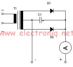
This simple lead-acid battery charger requires a center-tapped transformer (12V 0V 12V) capable of delivering a current of 5 amperes, two diodes, and one capacitor. To charge the batteries, the positive and negative terminals from the charger must be...
A constant-current/constant-voltage linear charger for single-cell lithium-ion (Li-ion) batteries can be constructed using the EUP8054 battery charger controller chip and a few passive components. This compact integrated circuit is suitable for various portable devices and is compatible with USB...
Application note on designing linear and switch-mode (switching DC-DC converter current source) battery charger applications that require external microcontrollers and related system-level issues for notebook computers. The application note provides guidance on the design of both linear and switching DC-DC...
Lead acid battery charger schematic using IC LM317. This lead acid battery charger circuit is simple to build and can be fit in a small box. The lead acid battery charger circuit utilizing the LM317 integrated circuit (IC) is a...