
Battery ChargerCircuit Using IC 555

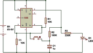
The battery charger circuit employs the 555 timer IC in astable mode to generate a PWM (Pulse Width Modulation) signal, which is crucial for controlling the charging process. The charging current can be adjusted by varying the resistor and capacitor values connected to the 555 timer, allowing for flexibility in charging different types of batteries, such as NiMH, Li-ion, or lead-acid.
The circuit typically includes a power supply input, which can range from a standard wall adapter to a solar panel, providing the necessary voltage and current for charging. The output of the 555 timer is connected to a transistor or a MOSFET, which acts as a switch to regulate the current flowing to the battery. A diode may also be included to prevent reverse current flow when the charging source is disconnected.
Additionally, the design may incorporate a voltage divider circuit for monitoring the battery voltage, ensuring that the charging process does not exceed the safe limits for the specific battery type. This can prevent overcharging, which could lead to battery damage or reduced lifespan.
For enhanced functionality, the circuit can include an LED indicator to signal the charging status, providing a visual cue that the battery is being charged. Overall, this simple yet effective battery charger circuit design is suitable for various applications, offering a practical solution for charging rechargeable batteries efficiently and safely.The simple battery charger circuit design shown here uses the versatile IC 555 as the main component. The circuit can be used for charging all types of rechargeable batteries within the specified limits as given in the article.
🔗 External reference
Related Circuits
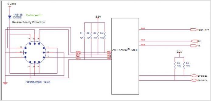
The M-8880 is a complete DTMF Transmitter/Receiver that features adjustable guard time, automatic tone burst mode, call progress mode, and a fully compatible 6500/6800 microprocessor interface. The receiver portion is based on the industry-standard M-8870 DTMF Receiver, while the...
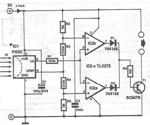
This infrared detector circuit is designed using the PID20 integrated circuit manufactured by Siemens, which converts thermal radiation into electrical impulses. It includes an operational amplifier and several electronic components. The output signal at pin 3 is compared with...
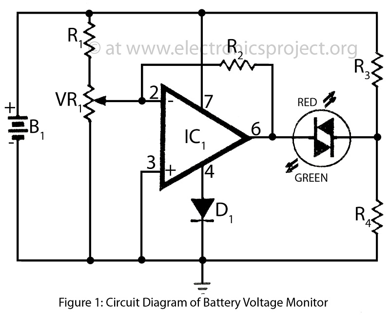
Battery voltage monitor is utilized to indicate the voltage level of a 12-volt battery circuit, specifically in a verified electronics project circuit. The battery voltage monitor circuit is designed to provide a visual representation of the voltage level of a 12-volt...
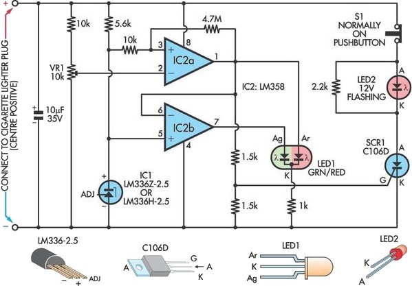
A car battery deteriorates with use, typically lasting no more than four years. Initially, its voltage may drop to just 2V when cranking the engine. As the battery ages, its internal impedance increases, leading to a higher voltage drop...
As shown in figure 14-17, this circuit consists of the input circuit, the line frequency synchronization generator, the sample-and-hold circuit, the voltage control delay generator, and the RF modulator. The input circuit includes the input attenuator RP1 and the...
The circuit functions as a toggle switch, exhibiting two stable states: ON and OFF. When the circuit is in the ON state, it remains in that state until the switch is pressed again. The project is based on a...