
Battery Indicator based on PIC18f452

To implement the described circuit, a microcontroller can be utilized to manage the operations of the keypad and the seven-segment display. The microcontroller should be programmed to handle the logic for detecting the state of the diode and transistor, as well as managing the keypad inputs and updating the display accordingly.
The diode testing circuit can be constructed using a simple arrangement of resistors and the microcontroller's GPIO pins. The diode can be connected in series with a resistor to limit the current. The microcontroller's pins can be configured as inputs or outputs based on the testing phase. The readings from the pins will determine the state of the diode.
For the transistor testing, a similar approach can be taken where the microcontroller tests the BE and BC junctions by controlling the respective pins and reading the results. The results will help determine the functionality and type of the transistor.
The keypad can be connected in a matrix formation, allowing for efficient use of the available pins. The rows and columns of the keypad should be connected to the microcontroller's GPIO pins, with pull-down resistors ensuring that the columns are grounded when not activated. The microcontroller should continuously poll each column to detect which button is pressed.
The seven-segment display will be driven by the microcontroller outputs. Depending on the type of display, the common pin should be connected appropriately, either to Vcc for common anode or ground for common cathode. The segments of the display will be driven by the microcontroller pins, allowing for the representation of numbers based on the keypad inputs.
This combination of components and logic provides a comprehensive solution for testing diodes and transistors while also allowing for user interaction through a keypad and visual feedback via a seven-segment display.If both the reading are high then the diode is short. If both the readings are Low then the diode is open. If any of read pins are low and the second is high then the diode is good. This concept can be easily extended to test a transistor by realizing that a transistor consists of two PN junctions: one between the base and the emitter (BE junction ), and the another between the base and the collector (BC junction). If both the junctions conduct in only one direction, the transistor is normal, otherwise it is faulty. We can also identify the type (PNP or NPN) of the transistor by considering the direction of the current conduction.
Three I/O pins of a microcontroller are required to implement the testing algorithm for a transistor. 2. Set D1 High and read D2. If D2 is High, EB junction conducts, otherwise not. Set D3 High and read D2. If D2 is High, CB junction conducts, otherwise not. Now, if only the BE and BC junctions conduct, the transistor is of NPN type and is working fine. And, if only the EB and CB junctions conduct, the transistor is still normal but the transistor type is PNP.
All other cases (like EB and BE both conduct, or BC and CB both not conducting, etc. ) indicate the transistor is not good. This project gives an idea that how we can interface the keypad and & Segment Display with PIC Microcontroller. When we press any digit from keypad, it will be displayed on the seven segment display. By pressing the # key, digit will increment and by pressing the * key, displayed digit will be decremented.
7 Segment Displays are of two types. Common Anode and Common Cathode. In Common Anode type display, Anode of each segment of display is common and we connect it to the Vcc or +5V. Whereas, cathode of each segment is available on the physical pins of 7 segment display as depicted in the following figure: I have used the common cathode type display.
Common pin is connected to the ground whereas pin a, b, c, . g are connected to PD0, PD1, PD2, . PD6 respectively. In a keypad there are physical switches for each number. Multiplexing technique is used to access the 12 keys with only 7 I/O pins. All the columns are pulled down through a resistor which means that a ground signal will always be on the pins connected to columns unless we apply a high through microcontroller. By the polling method, we keep sending high to the columns one by one and each time we send high to a column, we check all the four rows for a high signal.
Lets say, if button 6 is presses. Microcontroller will send a high to Col0, no high signal will be received on Row 0 to Row 3. Then it will send high to Col1, again no high signal will be received on Row 0 to Row3. Now it will send high to Col2, then a high signal will be received on Row1 which means that the button 6 is pressed. 🔗 External reference
Related Circuits
The circuit has been designed for telephone apparatus to indicate an incoming call as it rings using an LED for visual indication. BC550, an NPN general-purpose transistor, is utilized in the design. The circuit operates by detecting the ringing voltage...

The following diagram illustrates the circuit design of a Lead-Acid battery charger. This circuit provides an initial voltage of 2.5 V per cell at 25 °C to facilitate rapid charging of the battery. As the battery charges, the charging...
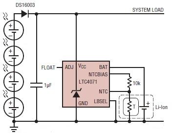
A simple solar-powered battery charger circuit can be designed using the LTC4071 Li-Ion/Polymer Shunt Battery Charger System with Low Battery Disconnect. When VCC reaches the programmed float voltage (4.1V with ADJ floating), the LTC4071 shunts excess current not used...
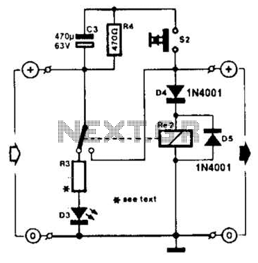
A charged capacitor C3 and a momentary pushbutton switch S2 are utilized to temporarily activate relay RE2. The battery being charged powers the relay to maintain its closed state. Additionally, S2 can energize the relay even if the battery...
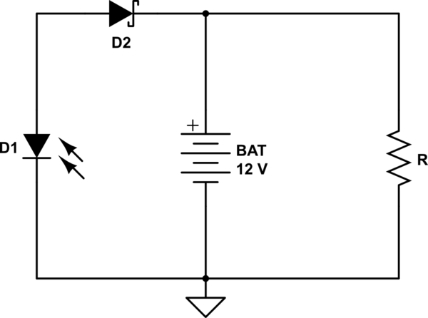
A 12V battery is charged using a solar panel. When the battery reaches 12V, the solar panel is disconnected from the battery, and the load is connected to the battery. The solar panel is reconnected to the battery when...
This circuit can be utilized as a replacement for the single current limiting resistor commonly found in inexpensive battery chargers. The alternative presented here will eventually... This circuit serves as an improved solution for current limiting in battery chargers, particularly...