
Relay Fuse For Battery Charges Circuit

In this circuit, capacitor C3 plays a crucial role in providing a temporary energy boost to relay RE2 when the momentary pushbutton switch S2 is pressed. The capacitor is charged prior to operation, allowing it to store electrical energy. When S2 is pressed, it connects the charged capacitor to the relay, supplying sufficient current to energize it momentarily.
Relay RE2 is designed to maintain its closed state once energized, which is facilitated by the battery under charge. This design ensures that even if the battery voltage is critically low, the relay can still be activated by the energy stored in capacitor C3. This feature is particularly useful in applications where the reliability of relay activation is essential, even under low battery conditions.
The circuit's operation can be broken down into two main phases: the charging phase, where capacitor C3 is charged from the battery, and the activation phase, initiated by pressing switch S2. During the charging phase, the capacitor accumulates energy until it reaches a threshold sufficient to activate the relay. In the activation phase, pressing S2 discharges the capacitor, sending a pulse of energy to the relay coil, thus closing the relay contacts.
This design highlights the importance of capacitors in providing short bursts of power, particularly in systems where battery performance may be compromised. The use of a momentary switch allows for precise control over the relay activation, ensuring that the relay only engages when necessary and does not remain in a powered state, which could lead to unnecessary battery drain. Overall, this circuit exemplifies an effective method of utilizing capacitors and relays in electronic designs, particularly in battery-powered applications. Charged capacitor C3 and momentary pushbutton switch S2 are used to momentarily energize relay RE 2. The batteiy under charge energizes the relay to hold it closed. S2 will energize the relay even if the battery is too far discharged initially to energize it.
Related Circuits
The Over-the-Top type of operational amplifier is ideal for use as a current sensor for battery charger applications. The design described here can be used with chargers for rechargeable batteries (Lead/acid or NiCd, etc.). The 5 V operating supply...
This circuit diagram illustrates a setup for two flashing LEDs designed for various applications, including model construction and recreational uses. It features adjustable flashing speeds controlled by two potentiometers. The circuit comprises a combination of active and passive components....
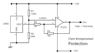
This is a basic overview of the LM35 temperature sensor, which is interfaced with an operational amplifier (op-amp) to boost its output. The LM35 provides a high output voltage when it detects high temperatures. The output can be utilized...
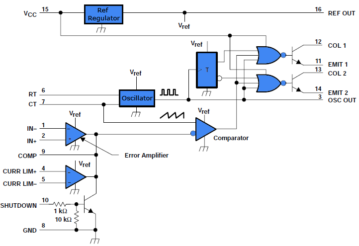
This document outlines a simple PWM (Pulse Width Modulation) DC to AC voltage inverter circuit based on the SG3524 integrated circuit. The SG3524 is a fixed frequency PWM voltage regulator control circuit that offers indifferent outputs suitable for both...
The circuit diagram presented illustrates an IC-controlled emergency light with a charger, functioning as a 12V to 220V AC inverter circuit. This emergency light circuit is designed to automatically activate in the event of a mains failure, while also...
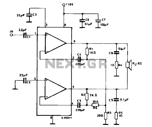
The schematic illustrates a 12 W Bridge Amplifier circuit diagram utilizing the TDA2007A, a class AB dual audio power amplifier. This amplifier is specifically designed for stereo applications in music centers, television receivers, and portable radios. As stated in...