
Battery Low Voltage Beeper

The circuit operates as a low voltage warning system specifically tailored for devices powered by a 12V battery. It utilizes a voltage comparator configuration wherein U1, likely an operational amplifier, is set to compare the voltage level from the battery against a predetermined reference voltage provided by U2. U2 generates a stable 5V output, which serves as the reference point for the comparator.
The adjustable resistor VR1 is employed to set the threshold voltage, which corresponds to the desired low voltage cutoff, typically around 11V. As the battery voltage decreases and dips below this threshold, the output of U1 transitions, triggering the visual and audible alarms.
The visual warning is indicated by an LED that illuminates when the voltage drops below the set point. Simultaneously, a speaker or piezo buzzer is activated to produce a periodic beeping sound, alerting users to the critical voltage level. This dual alert system ensures that users are promptly notified of the battery's status, allowing for timely intervention to prevent complete power loss.
The circuit is particularly well-suited for applications in solar power systems, where monitoring battery health is essential for maintaining operational efficiency. However, its design also lends itself to automotive applications and other scenarios where 12V battery systems are prevalent. This versatility makes the circuit a valuable addition to any low voltage monitoring toolkit.This circuit provides an audible and visual low voltage warning for 12V battery powered devices. When the battery voltage is above the set point (typically 11V), the circuit is idle. If the battery voltage should fall below the set point, the LED will light and the speaker will emit a periodic beeping sound to warn of the impending loss of power. The circuit was designed for monitoring solar systems, but it could also be useful for automotive and other 12V applications.
U2 provides a 5V regulated voltage reference. U1 is wired as a comparator, it compares the fixed 5V regulated voltage to the voltage on the wiper of VR1, that is proportional to the 12V supply. When the supply drops below the set point, the output of U1 g 🔗 External reference
Related Circuits
A PMOS FET switch regulator output is utilized in series with the regulator's load, as illustrated in the accompanying diagram. This represents a straightforward approach to circuit design. The described configuration employs a PMOS FET as a switching element in...
As the demand for VRM output current increases, the components and parts of the SR-Buck converter can no longer meet the requirements for the new generation microprocessors needing 100 A. Additionally, creating filtering inductance for high currents is quite...
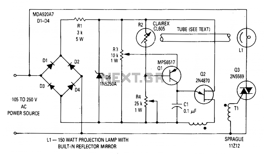
The circuit regulates the RMS output voltage across a load, specifically a projection lamp, to 100 volts ±2% for input voltages ranging from 105 to 250 volts AC. This regulation is achieved by indirectly sensing the light output of...
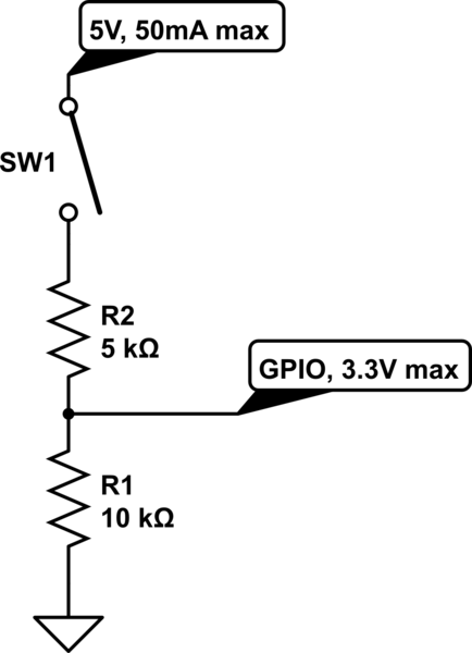
The circuit is designed to limit the maximum voltage between the GPIO input pin and the current source to 3.3V. This is achieved through a voltage divider configuration where the voltage across the 10K resistor is 3.3V, while the...
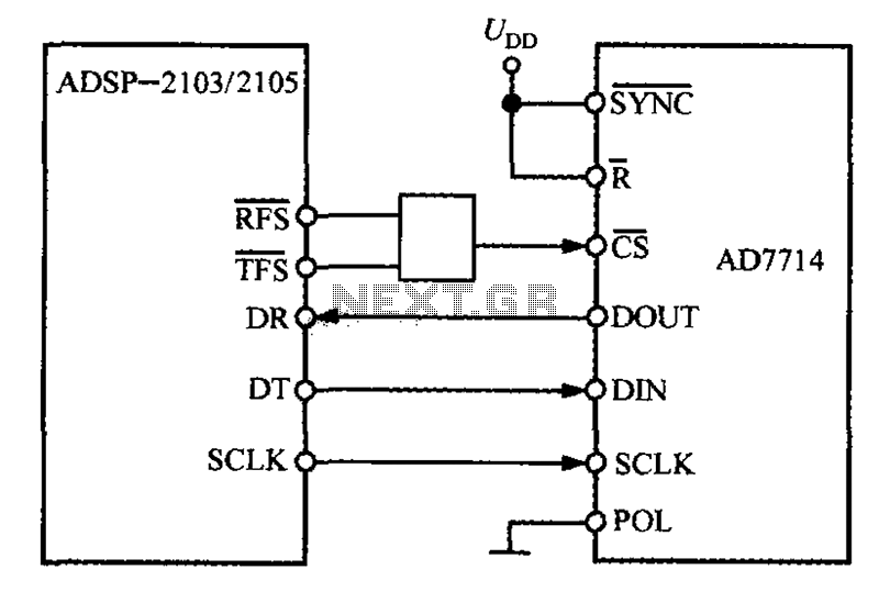
The ADSP-2103 and ADSP-2105 are digital signal processors that interface with the AD7714. When the output is active, the ADSP-2103/2105 configuration includes the RFS non-TES non-terminal set to a low level, while the SCLK terminal is configured for serial...
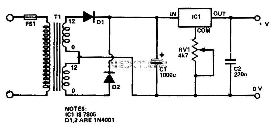
This circuit provides a regulated output voltage ranging from 5 V to 15 V DC, which can be adjusted using a preset resistor. The current output can reach up to approximately 350 mA. An integrated circuit is utilized to...