
PMOS FET Following The Output for Soft-Start Mechanism

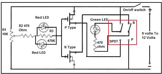
The described configuration employs a PMOS FET as a switching element in a linear regulator circuit. In this setup, the PMOS FET is positioned in series with the load, allowing for efficient control of the output voltage and current delivered to the load. The PMOS FET operates by switching on and off based on the control signal, which modulates the power supplied to the load according to the desired output characteristics.
In this arrangement, the gate of the PMOS FET is driven by a control voltage that determines whether the FET is in the on-state or off-state. When a positive voltage is applied to the gate relative to the source, the PMOS FET turns off, interrupting the flow of current to the load. Conversely, when the gate voltage is pulled low, the FET turns on, allowing current to flow through to the load.
The simplicity of this design lies in its minimal component count and straightforward operation. It is particularly advantageous in applications where low-power switching is required, as it can efficiently handle varying load conditions while maintaining a stable output voltage. Additionally, the use of a PMOS FET allows for high-side switching, which is beneficial in certain circuit configurations where the load needs to be connected to the positive supply rail.
In summary, the PMOS FET switch regulator configuration offers an effective and uncomplicated method for regulating output voltage in electronic circuits, making it suitable for a wide range of applications in power management systems.Using the following PMOS FET switch regulator output, in series with the regulator`s load as shown in the picture below is the most simple method. Switch.. 🔗 External reference
Related Circuits
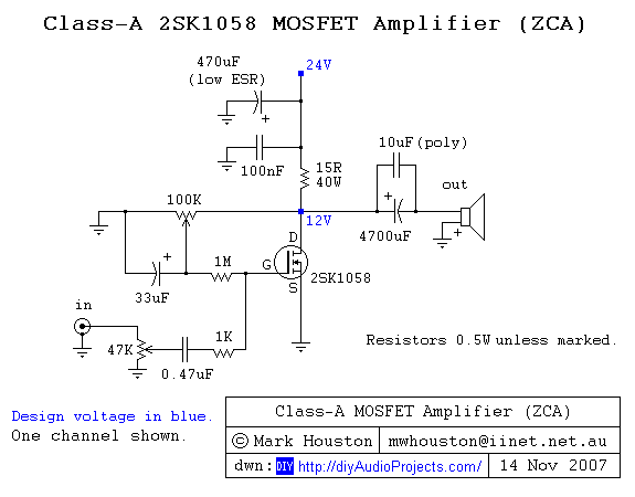
A straightforward DIY Class-A MOSFET amplifier project that utilizes a single Hitachi 2SK1058 N-channel MOSFET in a single-ended configuration. This Class-A MOSFET amplifier design is characterized by its simplicity and effectiveness, making it suitable for audio amplification applications. The core...
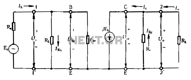
Calculate magnification, input resistance, and output resistance circuit. This circuit is designed to calculate the magnification, input resistance, and output resistance of a given electronic system. The magnification refers to the ratio of the output signal to the input signal,...
Field-effect transistors (FETs) are integral components found in various applications such as power sections, LCD inverters, uninterruptible power supplies (UPS), amplifiers, monitor B+ circuits, and ATX power supplies. When a FET fails, it is essential to use a meter...
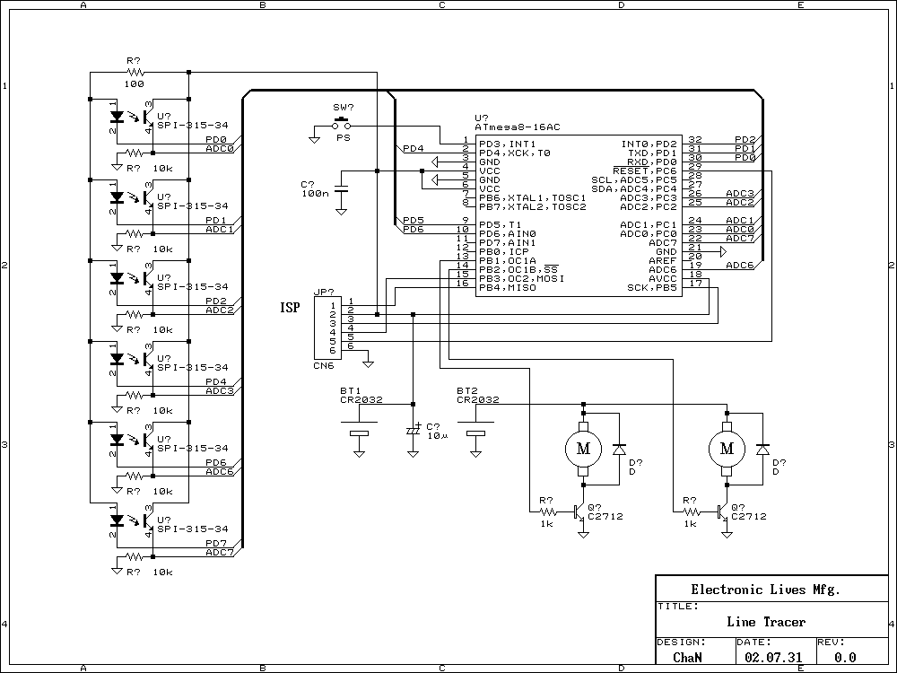
Recently many kind of robot contests have being opened and some interesting reports of the challenge are found on the web. The Line Following is a kind of the robot contests to vie running speed on the line. I...
This tester is designed to locate stray electromagnetic (EM) fields. It can easily detect both audio and RF signals up to frequencies of around 100 kHz. However, it is important to note that this circuit is not a metal...
The audio amplifier illustrated in this circuit diagram is a straightforward and efficient audio amplifier circuit based on the TDA1308 integrated class-AB stereo headphone amplifier. This device is manufactured using a 1 mm Complementary Metal Oxide Semiconductor (CMOS) process...