
meter adaptor with symmetrical

The described circuit utilizes an instrumentation amplifier to isolate the oscilloscope input from ground potential, thereby preventing ground loops and potential short circuits that could arise when measuring live circuits. The AD621 amplifier is selected for its high CMRR and bandwidth, making it suitable for precise measurements in noisy environments. The inclusion of a switch to select between three different measurement ranges allows for flexibility in various applications, ensuring that the oscilloscope can handle a wide range of signal amplitudes while maintaining accuracy.
The design considerations for resistors R1 and R8 emphasize the importance of voltage ratings, particularly in high-voltage applications, where exceeding the rated voltage could lead to component failure and safety hazards. The recommendation to use two series resistors rated for 300 V each is a practical solution that balances availability and safety. Additionally, maintaining a 1% tolerance for the resistors ensures that the measurements remain accurate and reliable.
The choice of power supply, whether from mains or batteries, adds versatility to the circuit's deployment. Battery operation is particularly beneficial in field applications where mains power is not accessible. The low current consumption of the circuit enhances battery life, making it suitable for prolonged use in remote locations.
Overall, this circuit design effectively addresses the challenges associated with oscilloscope measurements in grounded circuits, providing a safe and reliable means of obtaining accurate electrical measurements in a variety of settings.In contrast to an ordinary voltmeter, the input of an oscilloscope generally has one side (GND) connected to ground via the mains lead. In certain situations this can be very problematic. When the measuring probe is connected to a circuit that is also connected to ground, there is a chance that a short is introduced in the circuit.
That the circui t, and hence the measurement, is affected by this is the least of your problems. If you were taking measurements from high current or high voltage (valve equipment) circuits, the out-come could be extremely dangerous! Fortunately it is not too difficult to get round this problem. All you have to do is make the input to the oscilloscope float with respect to ground. The instrumentation amplifier shown here does that, and functions as an attenuator as well. The AD621 from Analog Devices amplifies the input by a factor of 10, and a switch at the input gives a choice of 3 ranges.
A GND` position has also been included, to calibrate the zero setting of the oscilloscope. The maximum input voltage at any setting may never exceed 600 VAC. Make sure that R1 and R8 have a working voltage of at least 600 V. You could use two equal resistors connected in series for these, since 300 V types are more easily obtainable. You should also make sure that all resistors have a tolerance of 1% or better. Other specifications for the AD621 are: with an amplification of 10 times the CMRR is 110 dB and the bandwidth is 800 kHz.
If you can`t find the AD621 locally, the AD620 is a good alternative. However, the bandwidth is then limited to about 120 kHz. The circuit can be housed inside a metal case with a mains supply, but also works perfectly well when powered from two 9V batteries. The current consumption is only a few milliamps. You could also increase R9 to 10 k to reduce the power consumption a bit more. 🔗 External reference
Related Circuits
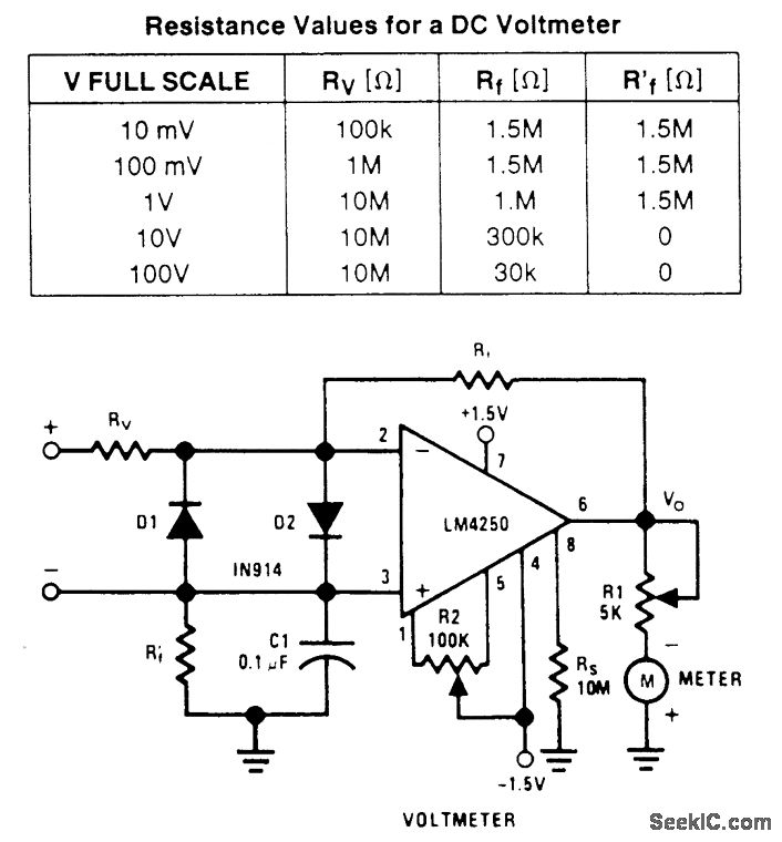
A wide-range voltmeter circuit. This inverting amplifier has a gain varying from -30 for the 10-mV full-scale range to -0.003 for the 100-V full-scale range. Diodes D1 and D2 provide complete amplifier protection for input overvoltages as high as...

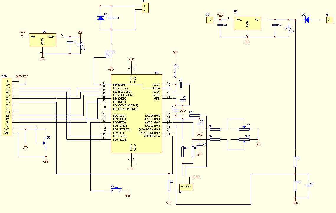
A prerequisite for this article is that the GCC AVR programming environment is installed as described in the article "Programming the AVR microcontroller with GCC, libc 1.0.4." To avoid installation issues, using the AVR programming CD is recommended. When...
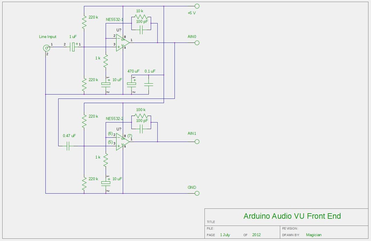
After experimenting with a stereo version of the VU meter described in a previous blog post, a studio-grade VU meter is now being presented. This meter features 24 steps, spaced equally every 3 dB, and covers a wide dynamic...
This multimeter was designed to measure output voltage and current in a PSU, where the current sense shunt resistor is connected in series with load at the negative voltage rail. It needs only one supply voltage that can be...

The 555 timer IC serves as the core component of the circuit, tasked with charging an unknown capacitor (Cx) to a predetermined voltage. Following this, the capacitor discharges into a meter circuit, which measures the current flowing through a...
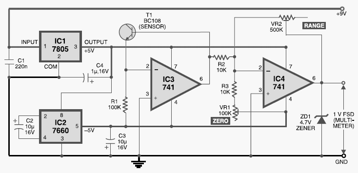
This digital thermometer circuit diagram uses a common 1N4148 diode as the temperature sensor. The temperature coefficient of the diode is -2 mV/°C. The digital thermometer circuit leverages the characteristics of the 1N4148 diode, which has a well-defined temperature coefficient....