
Battery Powered Burglar Alarm Sensor Circuit

This battery-powered burglar alarm sensor circuit is designed to provide an effective security solution for residential and commercial properties. The primary components of the circuit include a passive infrared sensor (PIR), which detects motion by sensing changes in infrared radiation emitted by objects within its range. Additionally, magnetic reed contacts are employed to monitor the opening and closing of doors or windows, enhancing the overall security system.
The circuit operates on a low-voltage battery, ensuring that it remains functional during power outages. The PIR sensor is typically mounted in a location that covers the entrance or area to be monitored, and it is configured to trigger an alarm when motion is detected. The alarm can be an audible sound, a visual indicator, or a notification sent to a mobile device, depending on the specific design and components used.
Foil tape serves as a simple and effective means to create a conductive path that can be used in conjunction with the magnetic reed contacts. When a door or window is opened, the magnetic field is disrupted, causing the circuit to activate the alarm. This dual-layered approach of using both PIR sensors and magnetic contacts ensures that the system is robust and capable of detecting unauthorized entry through various means.
The circuit design may also incorporate additional features such as a delay timer to prevent false alarms caused by pets or small animals, and an adjustable sensitivity setting for the PIR sensor to cater to different environmental conditions. Overall, this battery-powered burglar alarm sensor circuit offers a reliable and efficient method for enhancing security in various settings.The following circuit shows about Battery Powered Burglar Alarm Sensor Circuit. Features: foil tape and PIRs, such as magnetic-reed contacts, .. 🔗 External reference
Related Circuits
This is the lowest cost dialing alarm on the market and shows what can be done with an 8-pin microcontroller. The complete circuit is shown below. You cannot see all the features of this project by looking at the...
Here is a deluxe version of the simple charge rate limiter, using the same idea but with the ability to charge two packs simultaneously from a single wall charger. For circuit description and parts list, see the simple charger...
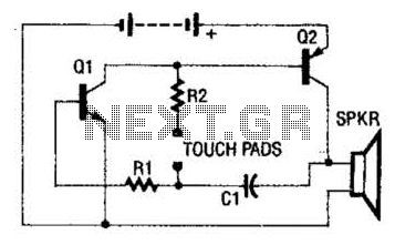
The circuit employs a two-transistor direct-coupled oscillator, with its frequency determined by capacitor C1, resistor R2, and the skin resistance across the touch pads. Since C1 and R2 are fixed values, only the skin resistance can vary the sound...
The Proteus files can be found. Recently, four pairs of ultrasound MA40S4 receivers/transmitters from Murata were purchased. They function as a pair of ultrasound microphones and speakers. The objective is to build a simple homemade ultrasound sensor for detecting...
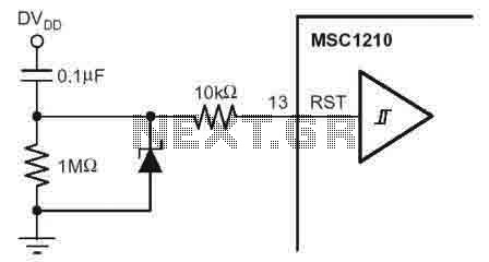
According to the MSC1210 datasheet, you will perform an external reset by taking RST pin high for two tOSC periods as this stops device operation, crystal oscillation, causes all digital pins to be pulled high from that point and...
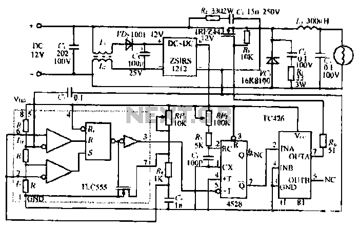
The circuit utilizes a Bute CD12V Lee power MOSFET transistor (BU1RF744) that operates in a switching mode, turning on and off repeatedly. The output voltage is influenced by the characteristics of the MOSFET, which is designed for efficient performance....