
Battery Powered Electret Microphone Pre-Amplifier

The electret microphone pre-amplifier circuit is designed to amplify the weak audio signals generated by an electret microphone. The LMV721 op-amp serves as the core amplification component due to its favorable specifications, including low noise operation and minimal power consumption, making it suitable for battery-powered applications.
The circuit typically includes the electret microphone, which contains a built-in FET that converts sound waves into electrical signals. The output from the microphone is connected to the non-inverting input of the LMV721. A resistor-capacitor (RC) network may be employed to filter out high-frequency noise and stabilize the gain. The gain of the amplifier can be adjusted by selecting appropriate feedback and input resistors.
Power supply considerations are critical; the LMV721 can operate with a single supply voltage, which simplifies the design. Bypass capacitors are recommended close to the power supply pins of the op-amp to reduce power supply noise. The output of the LMV721 can then be interfaced with further audio processing stages or directly with an analog-to-digital converter (ADC) for digital audio applications.
Overall, this schematic provides an efficient solution for amplifying audio signals in various applications, including voice recognition systems, portable audio devices, and other low-power audio applications.Here is a schematic diagram of electret microphone pre-amplifier using LMV721 op-amp. because the LMV721 has low noise and low power features, it would be an. 🔗 External reference
Related Circuits
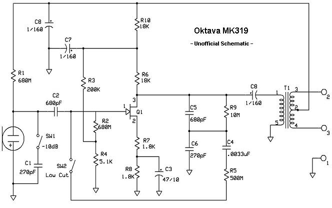
The MK-319 is a fixed cardioid-pattern, large-diaphragm condenser microphone. The capsule assembly is the same as the MK-219; the primary differences between the models are that the diaphragm is gold-sputtered Teflon, mounted to a center-terminated capsule design. The rear...

A simple yet reliable car battery tester circuit diagram. This circuit utilizes the popular and easily accessible LM3914 integrated circuit (IC). The LM3914 is straightforward to operate, does not require external voltage regulators due to its built-in voltage regulator,...
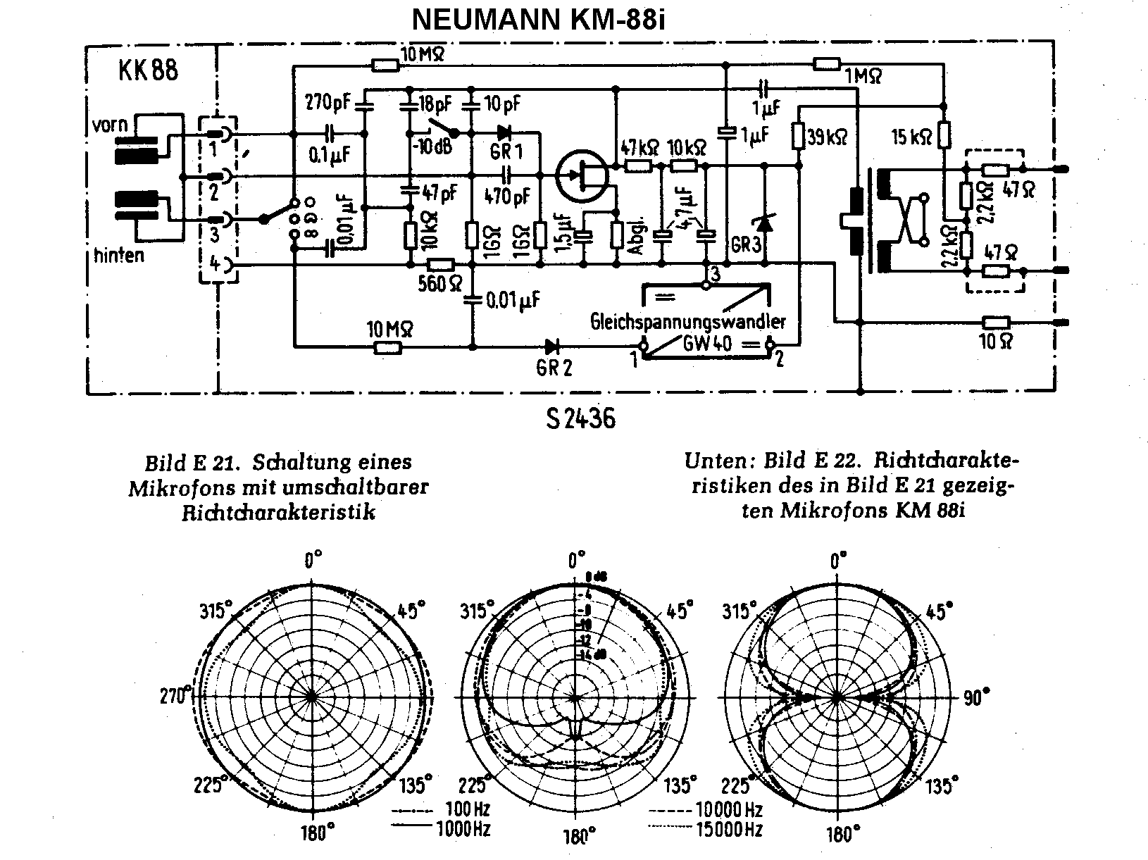
Both microphones, along with the stereo mics SM2 and SM23, utilized a similar basic capsule design akin to the KM54 capsule. According to Klaus Heyne of German Masterworks, the FET KM88 was created to utilize the company's surplus of...

Lithium-based (Li+) batteries are increasingly used in portable devices due to their favorable characteristics. However, they are often in limited supply, leading to long lead times unless a preferred-customer status is established with manufacturers. Consequently, a backup alternative to...
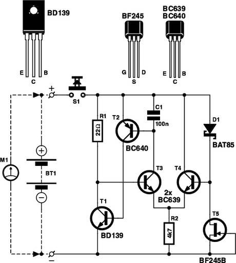
Determining whether a battery is empty or if there is a fault with a device can be challenging when a battery-powered device, such as a Walkman, fails to power on. Before seeking professional repair, it is advisable to test...
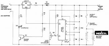
This circuit illustrates a Lithium Battery Charger circuit diagram. Charging is achieved using a constant current of 60 mA for AA cells until a cutoff voltage of 2.4V per cell is reached, at which point the charging process must...