
Lithium Battery Charger Circuit With LM317 IC

The Lithium Battery Charger circuit employs an LM317 voltage regulator, which is configured to provide a constant output current suitable for charging AA lithium cells. The design ensures that the charging current remains stable at 60 mA, which is optimal for maintaining battery health and efficiency during the charging process.
The circuit includes a diode to prevent reverse current flow, which could damage the power source or the battery being charged. A resistor is used to set the charging current, while a capacitor may be included for smoothing the output voltage and filtering any noise that could affect the charging performance.
The transistor in the circuit acts as a switch, which can be controlled to enable or disable the charging process based on the battery voltage levels. This feature is crucial for preventing overcharging, which can lead to battery degradation or failure. Once the voltage of the lithium cell reaches 2.4V, the circuit is designed to terminate the charge automatically, ensuring the safety and longevity of the battery.
The switch allows for manual control of the charging process, providing flexibility in operation. Overall, this circuit is an effective solution for safely charging lithium batteries while maintaining optimal performance through well-designed components and configurations.This circuit shows a Lithium Battery Charger circuit diagram. Charging is accomplished with a constant current of 60 mA for AA cells to a cutoff of 2. 4V per cell, at which point the charge must be terminated. Component: LM317 IC, Diode, Resistor, Capacitor, Transistor, Switch, Battery. [circuitdiagram. net] 🔗 External reference
Related Circuits
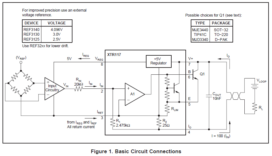
A simple circuit is required to simulate sensor inputs to a PLC. The sensors operate at 12VDC and output a current of 4-20mA. The XTR series devices are being considered for this application, but clarification is needed regarding which...

A GdS cell serves as one leg of a bridge circuit. Potentiometer R6 in another leg establishes the trip point. Potentiometer R5 allows for hysteresis adjustment to prevent chattering or hunting of the relay. The light level must increase...
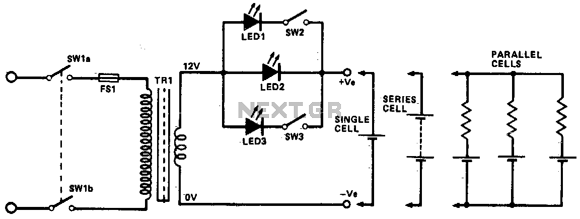
This circuit utilizes constant current LEDs to regulate the charging current. It employs LEDs that maintain a consistent current of approximately 15 mA across an applied voltage range of 2 to 18 V. The LEDs can be connected in...
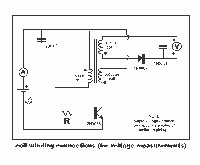
New Jewel Thief "Resonate LCR Circuit" with significantly reduced energy consumption. Measurements of voltage and current for the Joule thief. The Jewel Thief circuit, particularly the "Resonate LCR Circuit," is an innovative low-power design that enhances energy efficiency while maintaining...
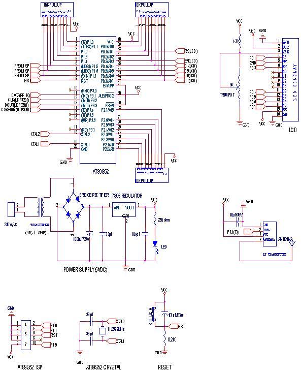
RF Wireless Data Transfer communication circuit diagram. A wireless communication interface was implemented to facilitate data transfer from one point to another using RF technology. The RF Wireless Data Transfer communication circuit utilizes radio frequency (RF) technology to establish a...
Delay starting a motor control circuit The motor control circuit designed for delayed activation incorporates a timing mechanism that ensures the motor does not start immediately upon receiving power. This is particularly useful in applications where a staggered startup...